


8
User's Guide HDSP System Multiface II © RME
5.3 Notes on Power Supply
• The CardBus card delivers no power to the Multiface. Therefore a hi-tech switching power
supply is included.
• The PCI card operates as power supply for the attached Multiface via the FireWire cable. An
external power supply is not required.
The Multiface II draws a high startup current of more than 2 A during initialisation. Current at 12
Volt operating voltage: unloaded 720 mA (8.6 Watts), loaded 1 A (12 Watts). Supply voltage
range DC 8 V – 28 V, AC 8 V – 20 V.
The Multiface II has a higher power consumption as the original Multiface. Therefore the
Multiface II will only work with a HDSP PCI card revision 1.9 or higher!
While the Multiface causes a load of about 9 Watts to the PCI card, the Multiface II will cause a
load of about 12 Watts. The HDSP PCI cards built until recently are not designed for such a
load. The voltage regulator found on the PCI card will switch off after a short time due to over-
heating. The HDSP PCI revision 1.9 uses a more powerful regulator.
Still the Multiface II can also be used with an older HDSP PCI card, in case the Multiface II is
powered by an external power supply. With a voltage higher than 10 Volts, the power supply of
the PCI card is automatically switched off. We recommend the RME switching power supply 12
V / 1.25 A, included with the CardBus card, but also available separately.
6. First Usage – Quick Start
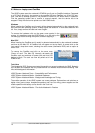
6.1 Connectors and Front Panel
The front of the Multiface II features a MIDI input and output, a stereo headphone output with
volume control, two switches to select the analog reference level, and several status LEDs.
MIDI IN and OUT represent the MIDI input and output, realized as 5-pin DIN jacks.
The LEDs MIDI IN and OUT indicate sent or received data for the MIDI ports.
The Digital State LEDs (WC, SPDIF, ADAT) indicate a valid input signal separately for each
digital input. Additionally, RME's exclusive SyncCheck indicates if one of these inputs is locked,
but not synchronous to the others, in which case the LED will flash. See also chapter 11.2 /
20.2, Clock Modes - Synchronization.
The red HOST LED lights up when the power supply or the computer is switched on, thus sig-
nalling the presence of operating voltage. At the same time it operates as Error LED, in case
the I/O-box wasn’t initialised, or the connection to the interface has been interrupted (Error,
cable not connected etc.). It flashes then. After the firmware had been loaded the LED turns off,
thus signalling a proper operation.
ANALOG LEVEL has two switches with three positions each, to select the reference level of
the eight analog inputs and outputs on the rear.
Phones is a low impedance line output of highest quality, which can produce a sufficient vol-
ume undistorted even when used with headphones.
The volume of the phones output is adjusted with the pot VOL.