


50
User's Guide HDSP System Multiface II © RME
27. Word Clock
27.1 Technical Description and Usage
In the analog domain one can connect any device to another device, a synchronization is not
necessary. Digital audio is different. It uses a clock, the sample frequency. The signal can only
be processed and transmitted when all participating devices share the same clock. If not, the
signal will suffer from wrong samples, distortion, crackle sounds and drop outs.
AES/EBU, SPDIF and ADAT are self-clocking, an additional word clock connection in principle
isn't necessary. But when using more than one device simultaneously problems are likely to
happen. For example any self-clocking will not work in a loop cabling, when there is no 'master'
(main clock) inside the loop. Additionally the clock of all participating devices has to be syn-
chronous. This is often impossible with devices limited to playback, for example CD players, as
these have no SPDIF input, thus can't use the self clocking technique as clock reference.
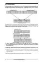
In a digital studio synchronisation is maintained by connecting all devices to a central sync
source. For example the mixing desk works as master and sends a reference signal, the word
clock, to all other devices. Of course this will only work as long as all other devices are
equipped with a word clock or sync input, thus being able to work as slave (some professional
CD players indeed have a word clock input). Then all devices get the same clock and will work
in every possible combination with each other.
Remember that a digital system can only have one master!
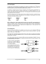
27.2 Cabling and Termination
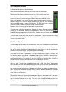
Word clock signals are usually distributed in the form of a network, split with BNC T-adapters
and terminated with resistors. We recommend using off-the-shelf BNC cables to connect all
devices, as this type of cable is used for most computer networks. You will find all the neces-
sary components (T-adapters, terminators, cables) in most electronics and/or computer stores.
Ideally, the word clock signal is a 5 Volt square wave with the frequency of the sample rate, of
which the harmonics go up to far above 500 kHz. To avoid voltage loss and reflections, both the
cable itself and the terminating resistor at the end of the chain should have an impedance of 75
Ohm. If the voltage is too low, synchronization will fail. High frequency reflection effects can
cause both jitter and sync failure.
Unfortunately there are still many devices on the market, even newer digital mixing consoles,
which are supplied with a word clock output that can only be called unsatisfactory. If the output
breaks down to 3 Volts when terminating with 75 Ohms, you have to take into account that a
device, of which the input only works from 2.8 Volts and above, does not function correctly al-
ready after 3 meter cable length. So it is not astonishing that because of the higher voltage,
word clock networks are in some cases more stable and reliable if cables are not terminated at
all.
Ideally all outputs of word clock delivering devices are designed with very low impedance, but
all word clock inputs with high impedance, in order to not weaken the signal on the chain. But
there are also negative examples, when the 75 Ohms are built into the device and cannot be
switched off. In this case the network load is often 2 x 75 Ohms, and the user is forced to buy a
special word clock distributor. Note that such a device is generally recommended for bigger
studios.