


Philips Semiconductors
User Manual of High-End RDS/EON
Car Radio System CCR612 (V0.3)
Application Note
96029
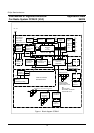
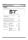
2.1.4 Main Board Part 2a ( Micro-controller, EEPROM and RDS Demodulator)
Page 84 shows the circuit diagram of the RDS Demodulator, Micro controller (which combines all radio
control functions as well as RDS decoding) and EEPROM.
Microcontroller (P83CE528EFB)
Main microcontroller (CCR612S), a derivative of the 8051 micro-controller family with an 8-bit CPU, 32
Kbytes ROM, 512 bytes RAM and four 8-bits I/O ports in a 44-pins QFP package.
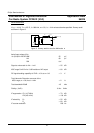
EEPROM (PCF8594E-2P/T)
The PCF8594Eis a512 byte,5V Electrically ErasableProgrammable ReadOnly Memory(EEPROM) that
can be 100,000 times re-written. I
2
C-bus controlled.
RDS Demodulator (SAA6579T)
RDS Demodulator IC, which includes the 57 kHz band-pass-filter, to generate the RDS data out of the
MPX signal.
2.1.5 Main Board Part 2b (Detachable Front)
Page 85 shows the previous circuit diagram (paragraph 2.1.4) of the micro controller board extended with
the possibility to use a detachable front panel.
2.1.6 Main Board Part 3 (Cassette Interface including Dolby B*)
Page 86 shows the circuit diagram of the cassette interface circuit for the Philips cassette deck P6-29/3.
The circuit is based on the TEA0675, Dual Dolby* B-type noise reduction circuit for playback applications.
The TEA0675 includes head and equalization amplifiers with electronically switchable time constants.
Furthermore the TEA0675 includes electronically switchable inputs for tape drives with reverse heads.
This device also detects pauses of music in the AMS (Automatic Music Search) scan mode.
16