


Philips Semiconductors
User Manual of High-End RDS/EON
Car Radio System CCR612 (V0.3)
Application Note
96029
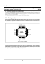
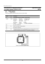
Pinning CCR612S
Pin Name I/O Type Description
8 RDSCLK I IP 1 RDS Clock line. Connected to clock output pin of RDS
demodulator SAA6579
9 CDC_bus I IP 1 CD-changer bus. The CDC_bus is a bi-directional bus
which allows the CD-changer and the radio to exchange
commands and status information.
10 BLPTST O
I
IP 1 1. Bleep tone output signal. Normally high. This pin
outputs the bleep tones.
2. When pulled low externally, service mode is entered.
The microcontroller stops all I
2
C bus transfers after
completion of the last user action (within 0.5 sec.
except for search tuning). This feature can be used for
factory testing and programming the NVM before the
radio leaves the factory.
11 CDOLBY O
I
IP 1 Cassette Dolby mode
High: Dolby not selected
Low: Dolby selected
If the cassette deck does not have this function, the pin
must be connected to Vdd.
12 RDSDAT I IP 1 RDS Data line. Connected to data output pin of RDS
demodulator SAA6579.
13 SEL0_
SOLENOID
O
O
I
IP 1 SEL0 (no TEA632x installed). Source selection
Sel1 Sel0
0 0 CD-changer source selected
0 1 Cassette source selected
1 0 External source selected
1 1 Radio source selected
SOLENOID (TEA632x installed). Cassette solenoid
High: Solenoid in standby position
Low: Solenoid is locked
If the cassette deck does not have this function, the pin
must be connected to ground.
14
15
XTAL2
XTAL1
O
I
A 12 MHz crystal is connected between these pins,
controlling the internal clock oscillator. When an external
clock is used, it must be applied to XTAL1.
16 Vss Ground
17 Vdd Power supply: + 5V
18-
24
IP 1 Keyboard scan lines. Pin assignments are different for
fixed front and detachable front. See relevant tables at the
end of this section.
32