


Philips Semiconductors
User Manual of High-End RDS/EON
Car Radio System CCR612 (V0.3)
Application Note
96029
CONTENTS
1 INTRODUCTION ............................................................... 11
1.1 Definitions, Acronyms and Abbreviations ...................................... 12
1.2 References .............................................................. 12
2 HARDWARE CONFIGURATION .................................................. 13
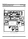
2.1 Block diagram CCR612 .................................................... 13
2.1.1 Main Board Part 1a (Basic AM/FM stereo Radio Part) ................... 13
2.1.2 Main Board Part 1b (Optional Power Amplifier, 2 x TDA8561Q) ........... 15
2.1.3 Main Board Part 1c (Optional Source Sel. & Audio Contr.
HEF4052B/TDA1526) ............................................. 15
2.1.4 Main Board Part 2a ( Micro-controller, EEPROM and RDS Demodulator) .... 16
2.1.5 Main Board Part 2b (Detachable Front) ............................... 16
2.1.6 Main Board Part 3 (Cassette Interface including Dolby B*) ............... 16
2.1.7 Front Panels ..................................................... 17
2.1.7.1 Front Panel Part FP-1a (Key and Display panel) .............. 17
2.1.7.2 Front Panel Part FP-1b (Detachable Front Version). .......... 17
2.1.8 Diagram ICE module. .............................................. 17
2.1.9 Diagram PACS Sub Board ......................................... 18
2.1.10 PCB LAY-OUTS of CCR612 sample Version D. ........................ 18
2.2 Performance of the radio ................................................... 19
3 SHORT SPECIFICATION ........................................................ 23
4 CCR612S PINNING AND INTERFACING ........................................... 30
4.1 Pinning overview .......................................................... 30
4.2 Factory options ........................................................... 38
4.2.1 Diode options .................................................... 38
4.2.2 Automatically detected options ...................................... 39
4.3 I
2
C bus addresses ......................................................... 39
4.4 The keyboard ............................................................ 39
4.4.1 Fixed keyboard ................................................... 40
4.4.2 Detachable keyboard .............................................. 40
4.4.3 Keyboard options ................................................. 41
4.5 Power stabilizer interface. .................................................. 42
4.6 LCD display. ............................................................. 44
4.7 Non Volatile Memory. ...................................................... 45
5 KEY FUNCTIONS .............................................................. 46
6 FUNCTIONAL DESCRIPTION .................................................... 57
6.1 Switching on / off .......................................................... 57
6.2 Tuning .................................................................. 58
6.2.1 Band switching ................................................... 58
6.2.2 Manual/search tuning ............................................. 58
6.2.3 Frequency scan .................................................. 60
5