


Philips Semiconductors
User Manual of High-End RDS/EON
Car Radio System CCR612 (V0.3)
Application Note
96029
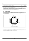
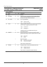
The next tables give a description of the function of all pins.
Legend for pin types: OD Open Drain
IP Internal Pull up resistor
1 Can sink 1 TTL load (or 4 LSTTL)
2 Can sink 2 TTL loads (or 8 LSTTL)
Pinning CCR612S
Pin Name I/O Type Description
1 EXSTAT I IP 1 Indicates whether external audio source is connected.
High: external audio source is not connected
Low: external audio source is connected
2 SCL I/O OD 2 Clock line of I
2
C bus
3 SDA I/O OD 2 Data line of I
2
C bus
4 RESET I Normally low. To start the microcontroller, a high pulse of
at least 20 milliseconds must be applied to this pin.
A reset pulse must be applied when:
- Power is applied to the radio
- The power key is pressed while the radio is off
- The ignition contact is switched on while the radio is off
The reset input is normally connected to the reset and hold
outputs of the power stabiliser TDA3602, via a capacitor
and a diode.
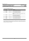
5 CMTL O
I
IP 1 Cassette Metal (versus Chrome/Ferro) mode
High: Ferro/Chrome selected
Low: Metal selected
If the cassette deck does not have this function, the pin
must be connected to Vdd.
6 Vss Ground
7 CAMS O
I
IP 1 Automatic Music Search
High: AMS is active
Low: AMS is inactive
If the cassette deck does not have this function, the pin
must be connected to ground.
31