


Philips Semiconductors
User Manual of High-End RDS/EON
Car Radio System CCR612 (V0.3)
Application Note
96029
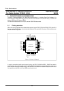
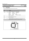
Pinning CCR612S
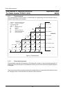
Pin Name I/O Type Description
25 HOLD I IP 1 Connected to the hold output pin of the voltage stabilizer
TDA3602. This pin is used to check for power failures.
26 /PSEN O Program Store Enable output, used when the
microcontroller runs code from an external memory. Not
used by the CCR612S system. The pin will always be high.
27 ALE O Address Latch Enable output, used when the
microcontroller accesses external memory. Not used by
the CCR612S system. This pin should not be connected.
In the EMC improved microprocessors (P83CE528) this
pin is muted.
28 Vss Ground
29 /EA I External Access input. Should be held high (with a pull-up
resistor) to ensure that the microcontroller runs from
internal program memory (ROM).
30 ON O OD 2 Controls the voltage stabiliser TDA3602
High: Switch supply voltages off (TDA3602 in "coma"
state)
Low: Switch supply voltages on (TDA3602 in "on"
state)
31 TA O
I
OD 2 Traffic Announcement indication
High: No traffic announcement
Low: Traffic announcement or PTY alarm message in
progress
This pin can be used to raise the volume setting during
traffic announcements and PTY alarm messages in case
no digital sound control IC is used.
Option diode for static on/off switch detection.
33