


Philips Semiconductors
User Manual of High-End RDS/EON
Car Radio System CCR612 (V0.3)
Application Note
96029
No digital sound control chip installed.
In this case, the keys VOL-UP, VOL-DOWN are not required.
The following keys are optional. If omitted, the related functionality is not available, but other functions
are not affected.
- AUTO/MANUAL (Function also available by pressing FREQ-UP and FREQ-DOWN together)
- LOUD (Loudness function also available in user programmable options; reset function
not available)
- DISPLAY
- PTY
- MUTE
- MODE
- SCAN
- LOCAL/DX
By means of an option diode, a selection can be made for a momentary power key (connected to port
KEYB0 and ground) or a static on/off key (connected between port IGN and ground).
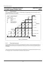
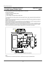
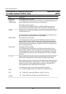
4.5 Power stabilizer interface.
For switching the radio on and off, the microcontroller is linked with the voltage stabilizer circuit TDA3602.
The pins involved in this interface are RESET, ON and HOLD.
Figure 8 shows a circuit diagram of the reset circuitry and the voltage stabilizer interface.
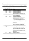
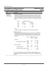
The TDA3602 hasa number of differentstates, which are selectedby the voltage onthe state controlinput
V
sc
on pin 4. The following states are used:
State V
sc
Description
OFF - No power
COMA > 3.6 V State when radio is off. Microcontroller supply is
in low current mode; other supply voltages are
off.
RESET 1.2V < V
sc
< 2.0V State during reset. Microcontroller supply is in
high current mode; other supply voltages are still
off.
ON < 1.2 V State when radio is on. All supply voltages are on.
To switch the radio on, the voltage stabilizer must be brought in reset state. It generates a reset pulse for
the microcontroller with its reset output pin. The microcontroller program starts, and decides whether the
radio must stay on or must switch off again. When it must stay on, output pin "ON" is pulled low, bringing
the TDA3602 in the "ON"state. Else, the stabilizer stays in resetstate, or returns to coma state eventually.
42