


Philips Semiconductors
User Manual of High-End RDS/EON
Car Radio System CCR612 (V0.3)
Application Note
96029
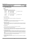
EURO 2, USA 1 and JAPAN 1 ICE MODULE VERSIONS.
By slight circuit modifications of the standard module (EURO 1), matched module versions with better
performance for e.g. USA an Japan can be derived. The needed modifications for the different modules
are:
Module Version Modifications.
Euro 1 Non
Euro 2 (including S.W.) A short wave transformer i.s.o. L8 and C29
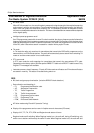
USA 1 L15 short circuited
C2 10pF i.s.o. 5p6
C72 6p8 deleted
R18 1 Mohm i.s.o. 220 Kohm
R54, in parallel with C26 (1uF)
C61 10 nF i.s.o. 6n8
C62 10 nF i.s.o. 6n8
Z1 SFR450H i.s.o. SFP 450H
Z3 SFE 10.7 MS3 G-A 220 kHz i.s.o. SFE10.7 MS3 A 10k-A
Z2 & Z4 SFE 10.7 MS2 G-A 180 kHz i.s.o. SFE10.7 MS3 A 10k-A
R41 (pre-set adjust) replaced by resistor of 68 Kohm.
R44 120 Kohm i.s.o. 82 Kohm.
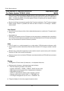
Japan 1 C7 47 pF i.s.o. 180pF
C9 deleted
D3 BB814 selection i.s.o. BB804
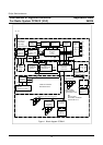
2.1.9 Diagram PACS Sub Board
Page 94 shows the diagram of the PACS Sub-Board using the TEA6850. For circuit description,
performance and PCB lay out see application note Ref.5.
2.1.10 PCB LAY-OUTS of CCR612 sample Version D.
CCR612/Mainboard PCB lay-out TOP side Copper (p. 90, fig. a) / Components (non SMD) (p. 90, fig. b)
CCR612/Mainboard PCB lay-out BOTTOM side Copper(p. 91, fig. c) / SMD Components (p. 91, fig.d)
ICE module board PCB lay-out TOP side Copper(p. 92, fig. a) /Components (non SMD) (p. 92, fig. b)
ICE module board PCB lay-out Bottom side Copper(p. 92, fig. c) / SMD Components (p. 92, fig. d)
Front panel PCB lay-out Top side Copper (p. 93, fig. a) / Components (non SMD) (p. 93, fig. b)
Front panel PCB lay-out Bottom side Copper (p. 93, fig. c) / SMD Components (p. 93, fig. d).
18