


Philips Semiconductors
User Manual of High-End RDS/EON
Car Radio System CCR612 (V0.3)
Application Note
96029
- Telephone mute circuit, between optrow (40) and Aumute (43) introduced.
- The use of one crystal (8.66 MHz) for both micro and RDS demodulator is not possible in this set.
Because for improved RDS behaviour more ’speed’ is needed which requires a crystal of 12 MHz
for the micro and 8.66 MHz or 4.33 MHz for the RDS demodulator.
- For part 2b only, in the lines ON/OFF, DATA and SCL between detachable front and micro ESD
protection circuits are introduced which consists of a few resistors, zener diode 5V6 (BZX79C) and
2 diodes (BAV99).
Key and Display panel SB1b (Page 21).
- Following a now a days trend the power switch, in the ON/OFF radio line,is moved to the detachable
front. That means two extra contacts on both detachable front and radio are needed.
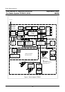
Diagram ICE Module (page 22).
- The diagram of the ICE module (Euro 1, standard) is modified, the "second" IC TEA6821 is replaced
by the successor TEA6822.
- The diagram of the ICE module (Euro 1, standard) is modified, the "second" IC TEA6821 is replaced
by the successor TEA6822.
Improvements of the TEA6822 with respect to the 6821:
At AM.
- Sensitivity higher. Distortion and AM and AF output less fieldstrength dependent
At FM.
- Interference Absorbtion improved by double detection.
- Gain less temperature dependent
- AM to FM switching in less then 0.5 seconds
With respect to software control.
- Level ADC extended from 3 to 4 bits.
- Multipath sensitivity to be set.
- Level temperature coefficient to be chosen (1 bit) for CDSP applications.
- Counter pre-scaler setting added to reduce counter time.
9