


Philips Semiconductors
User Manual of High-End RDS/EON
Car Radio System CCR612 (V0.3)
Application Note
96029
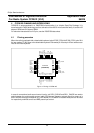
Pins 18-24 of CCR612 with detachable front
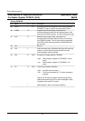
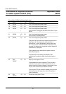
Pin Name I/O Type Description
18 KEYB0 I/O IP 1 Line of the triangular keyboard matrix
19 KEYB1 I/O IP 1 Line of the triangular keyboard matrix
20 KEYB2 I/O
I
IP 1 Line of the triangular keyboard matrix
Option diode for tuning grid and band limits (USA / Europe
option)
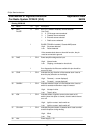
21 KEYB3 I/O
I
IP 1 Line of the triangular keyboard matrix
Option diode for available bands.
22 KEYB4 I/O IP 1 Line of the triangular keyboard matrix
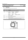
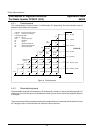
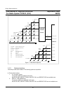
These lines form a small extra triangular keyboard matrix.
(See Figure 7). This keyboard is scanned every 10
milliseconds. To scan the keyboard, the lines are made
low - one at a time - and then the state of the other lines
are read. For debouncing, a keypress must be detected 3
times before it is accepted.
This keyboard can be used optional together with the
detachable keyboard.
The power key should always be available in this
keyboard but not when the static on/off switch option is
used.
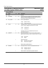
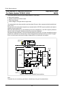
23 SDA_
FRONT
I/O IP 1 Data line of front panel I
2
C bus.
The detachable front has a separate I
2
C bus, for which
measures may be taken to reduce interference and to
improve immunity for static charges. It also isolates radio
circuitry from the externally accessible contacts.
The front panel I
2
C bus controls the display driver and the
8-bit bi-directional I/O expander to which the keyboard
matrix is detected.
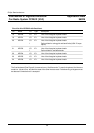
24 SCL_
FRONT
I/O IP 1 Clock line of front panel I
2
C bus.
37