


Philips Semiconductors
User Manual of High-End RDS/EON
Car Radio System CCR612 (V0.3)
Application Note
96029
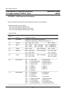
APPENDIX I NVM layout and initialisation
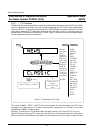
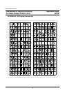
Words (16 bits) are stored with the most significant byte first (in lowest address).
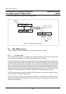
Ordering of the bits in a byte or word:
Bit 0 is the least significant (rightmost) bit
Bit 7 is the most significant (leftmost) bit of a byte
Bit 15 is the most significant (leftmost) bit of a word
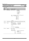
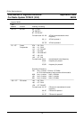
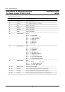
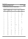
Layout of NVM
sub
address
function meaning / encoding
00 Checksum Checksum of two NVM check code bytes:
NVM check code byte(0) + NVM check code byte(1) + 2
01 Volume 00H = mute, 01H = -61 dB 3CH = +20 dB
02 Bass 00H = -15 dB 0AH = mid-range 14H = +15 dB(6320/2)
00H = -18 dB 0AH = mid-range 14H = +18 dB(6321/3)
03 Treble 00H = -12 dB 08H = mid-range 10H = +12 dB
04 Balance 00H = right muted 09H = mid range 11H = left -30 dB
01H = right -30 dB 12h = left muted
05 Fader 00H = front muted 09H = mid range 11H = rear -30 dB
01H = front -30 dB 12H = rear muted
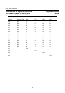
06 system status bit 0 0 = radio mode 1 = external mode
bit 1 0 = not cassette mode 1 = cassette mode
bit 2 0 = external plug in 1 = external plug not in
bit 3 0 = tape in drive 1 = tape not in drive
bit 4 0 = Dolby off 1 = Dolby on
bit 5 0 = AMS off 1 = AMS on
bit 6 0 = Me/Cr off 1 = Me/Cr on
bit 7 0 , not used
07 system status bit 0 0 = loudness off 1 = loudness on
bit 1 0 = 2-speakers 1 = 4-speakers
bit 2 0, not used
bit 3 0 = TA mode off 1 = TA mode on
bit 4 0 = Regional mode off 1 = Regional mode on
bit 5 0 = PTY mode off 1 = PTY mode on
bit 6 0 = no CD-changer 1 = CD-changer mode
bit 7 0 = no External source 1 = External source mode
72