


Philips Semiconductors
User Manual of High-End RDS/EON
Car Radio System CCR612 (V0.3)
Application Note
96029
2.1.7 Front Panels
2.1.7.1 Front Panel Part FP-1a (Key and Display panel)
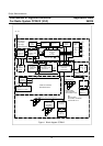
Page 87 shows the circuit diagram of the key and display panel.
LCD Driver (PCT8576CT)
The PCF8576 is a peripheral device which interfaces toalmost any liquid crystal display (LCD) having low
multiplex rates. It generates the drive signals for any static or multiplex LCD containing up to four back
planes and up to 40/24 segments and can easily be cascaded for larger LCD applications. I
2
C-bus
controlled.
2.1.7.2 Front Panel Part FP-1b (Detachable Front Version).
Page 88 shows the circuit diagram of the detachable keyboard front. The circuit includes an I/O expander
PCF8574, the keyboard and LCD display unit are placed on the detachable front controlled by a second
I
2
C bus. Eight contacts are required to connect the detachable front to the radio. Furthermore there is a
fixed key-board with a limited number of keys included. That means it is possible to use a combination of
detachable keys and fixed keys (for circuit example see page 85).
2.1.8 Diagram ICE module.
Standard Version EURO 1
Page 89 shows the complete circuit diagram of the ICE AM/FM tuner module version Euro 1.
The Standard Euro 1 module is intended for European frequency ranges.
FM 87.5 to 108.0 MHz
AM (MW) 531 to 1629 kHz
AM (LW) 144 to 288 kHz
The module contains the IC’s TEA6811V and TEA6822T with the following main functions;
TEA6811 - AM RF TEA6822 - 2
nd
AM mixer
- AM mixer - 2
nd
FM mixer
- FM mixer - AM/FM - IF amplifier
- AM/FM oscillator - AM and FM demodulator
- Tuning synthesizer - x-tal oscillator (61.5 MHz)
-I
2
C-Bus - Stereo Decoder and IAC
- Station (stop) detector
- Weak signal processing
- Multi Path Detector
-I
2
C-Bus
17