


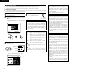
6
ENGLISH
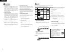
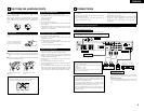
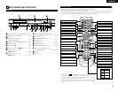
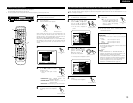
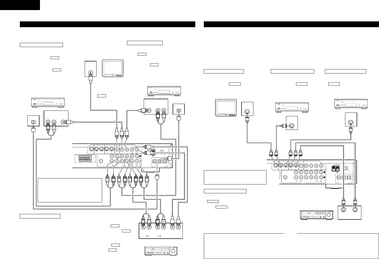
(2) Connecting video components
• To connect the video signal, connect using a 75 Ω/ohms video signal cable cord. Using an improper cable can result in a drop in
video quality.
• When making connections, also refer to the operating instructions of the other components.
IN
V.AUX
OUT
IN
TV/DBS
DIGITAL(OPTICAL)
IN OUTININ
TV/DBS
IN
V.AUX
VCR
MON.OUT
S VIDEO
IN OUTININ
TV/DBS
IN
V.AUX
VCR
MON.OUT
VIDEO
R
L
IN OUT IN ININ OUT
V.AUXTV/DBS VCR
CDR/
TAPE
PRE OUT
SUB WOOFER
AM
FM COAX. 75
LOOP ANT.
AUDIO
AV 1
VIDEO
OUT
AUDIO
OUT
L
R
VIDEO
OUT
INLR
OUT IN
L
R
AUDIO
OUT
OPTICAL
VIDEO
OUT
AUDIO
OUT
L
R
OUT
OPTICAL
VIDEO
IN
L
R
R
L
R
L
L
R
L
R
L
R
B
B
L
R
R
L
Connecting a TV/DBS tuner
TV/DBS
• Connect the TV’s or DBS tuner’s video output jack
(VIDEO OUTPUT) to the (yellow) TV/DBS IN
jack using a 75 Ω/ohms video coaxial pin plug cord.
• Connect the TV’s or DBS tuner’s audio output jacks
(AUDIO OUTPUT) to the TV/DBS IN jacks
using pin plug cords.
• For devices with optical digital outputs, connect the
digital output terminal to the ADV-1000’s DIGITAL
TV/DBS IN terminal using an optical transmission
cable.
AUDIO
VIDEO
TV or DBS tuner
Monitor TV
MONITOR OUT
• Connect the TV’s video input
jack (VIDEO INPUT) to the
MONITOR OUT jack
using a 75 Ω/ohms video
coaxial pin plug cord.
VIDEO
Connecting a CS tuner
V.AUX
• Connect the CS tuner’s video output jack (VIDEO OUTPUT)
to the (yellow) V.AUX IN jack using a 75 Ω/ohms
video coaxial pin plug cord.
• Connect the CS tuner’s audio output jacks (AUDIO
OUTPUT) to the V.AUX IN jacks using pin plug
cords.
• For devices with optical digital outputs, connect the digital
output terminal to the ADV-1000’s DIGITAL V.AUX. IN
terminal using an optical transmission cable.
AUDIO
VIDEO
CS tuner
Video deck
Note on connecting the digital input jacks
• Only audio signals are input to the digital
input jacks.
• Use optical cables for optical connections,
removing the cap before connecting.
Video input/output connections:
• Connect the video deck’s video output jack (VIDEO OUT) to the (yellow)
VCR IN jack, and the video deck’s video input jack (VIDEO IN) to the
(yellow) VCR OUT jack using 75 Ω/ohms video coaxial pin plug cords.
Connecting the audio output jacks
• Connect the video deck’s audio output jacks (AUDIO OUT) to the VCR IN
jacks, and the video deck’s audio input jacks (AUDIO IN) to the VCR OUT
jacks using pin plug cords.
AUDIO
AUDIO
VIDEO
VIDEO
Connecting a video decks
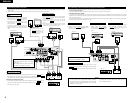
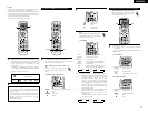
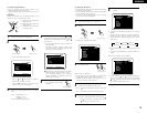
(3) Connecting a video component equipped with S-Video jacks
• When making connections, also refer to the operating instructions of the other components.
• A note on the S input jacks
The input selectors for the S inputs and pin jack inputs work in conjunction with each other.
• Precaution when using S-jacks
This unit’s S-jacks (input and output) and video pin jacks (input and output) have independent circuit structures, so that video
signals input from the S-jacks are only output from the S-jack outputs and video signals input from the pin jacks are only output
from the pin jack outputs.
When connecting this unit with equipment that is equipped with S-jacks, keep the above point in mind and make connections
according to the equipment’s instruction manuals.
Connecting a monitor TV
MONITOR OUT
• Connect the TV’s S video input (S-VIDEO
INPUT) to the MONITOR OUT
jack using a S jack connection cord.
S-VIDEO
IN
V.AUX
OUT
IN
TV/DBS
DIGITAL(OPTICAL)
IN OUTININ
TV/DBS
IN
V.AUX
VCR
MON.OUT
S VIDEO
IN OUTININ
TV/DBS
IN
V.AUX
VCR
MON.OUT
VIDEO
R
L
IN OUT IN ININ OUT
V.AUXTV/DBS VCR
CDR/
TAPE
PRE OUT
SUB WOOFER
AM
FM COAX. 75
LOOP ANT.
AUDIO
AV 1
S-VIDEO
IN
S-VIDEO
OUT
S-VIDEO
OUT
S-VIDEO
IN
S-VIDEO
OUT
B
B
Monitor TV
Connecting a TV/DBS tuner
• Connect the TV’s or DBS tuner’s S
video output jack (S-VIDEO
OUTPUT) to the TV/DBS
IN jack using an S jack connection
cord.
S-VIDEO
TV or DBS tuner
Connecting a CS tuner
• Connect the CS tuner’s S video output
jack (S-VIDEO OUTPUT) to the
V.AUX. IN jack using an S
jack connection cord.
S-VIDEO
CS tuner
Video deck
Connect the components’ audio inputs
and outputs as described on page 6.
Connecting the video decks
• Connect the video deck’s S output jack (S-OUT) to the
VCR IN jack and the video deck’s S input jack (S-IN)
to the VCR OUT jack using S jack connection cords.
S-VIDEO
S-VIDEO
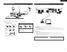
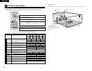
• Connect this unit video outputs to the TV either directly.
Do not connect it via a VCR (video cassette recorder).
Some discs contain copy prohibit signals. If such discs are
played via a VCR, the copy prohibit system may cause
disturbance in the picture.
• Set the “TV TYPE” in “VIDEO SETUP” in “DVD SETUP”
to comply with your TV’s video format. When the TV is
PAL formated set to PAL.
NOTES: