


SPAN-CPT Installation Chapter 2
SPAN-CPT User Manual Rev 8 17
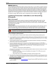
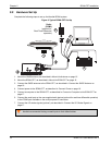
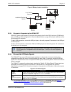
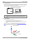
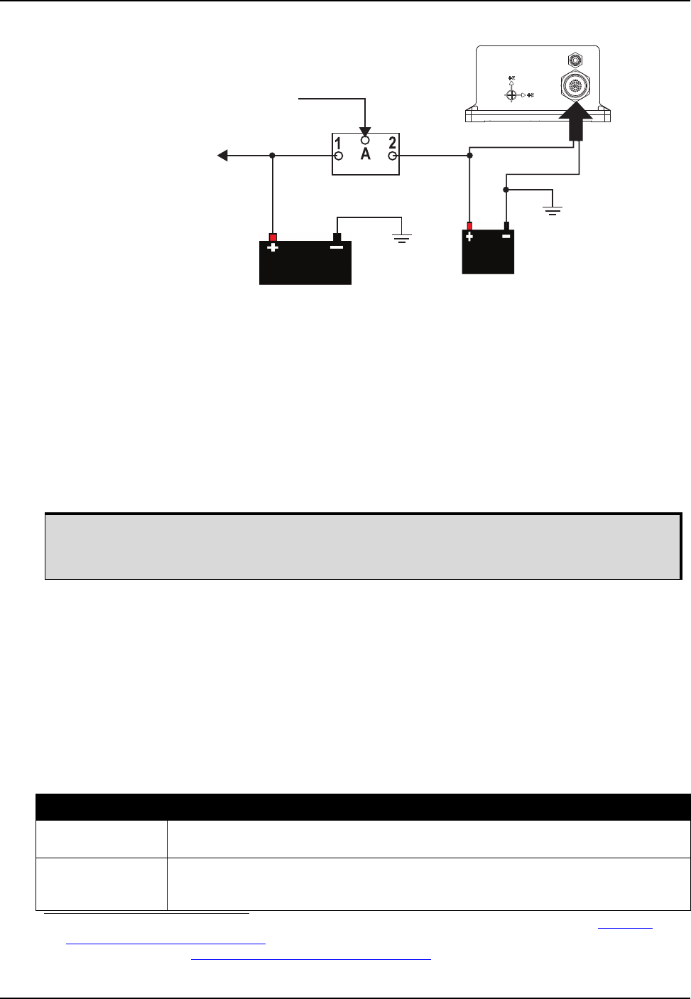
Figure 5: Battery Isolator Installation
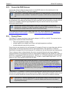
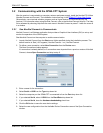
2.2.5 Connect a Computer to the SPAN-CPT
SPAN-CPT has a multi-purpose I/O connector that contains pins for the COM1 serial port, COM2 serial
port and USB port. Refer to Appendix A, Technical Specifications on page 48 for the pin definitions of the
multi-purpose I/O connector.
To use a USB connection, connect the USB port pins on the multi-purpose I/O connector to the USB port
on the computer.
To use a serial connection, connect the COM1 or COM2 port pins on the multi-purpose I/O connector to
the serial port on the computer.
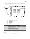
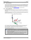
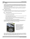
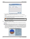
2.2.6 Connect the I/O Strobe Signals
The SPAN-CPT has several I/O strobe signals enabling it to be part of an interconnected system
composed of devices that need to be synchronized with each other. For example, connect the SPAN
system to an aerial camera in such a way that the SPAN system records its position whenever the shutter
button is pressed.
The SPAN-CPT supports the strobe signals described in Table 6, I/O Strobe Signals. These signals are
accessed from the multi-purpose I/O connector on the SPAN-CPT. See Appendix A, Technical
Specifications on page 48 for information on signals, wiring and pin-out information of the multi-purpose
I/O connector.
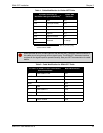
Figure 6: I/O Strobe Signals
from Vehicle
Alternator
to Vehicle Electrical
System
Vehicle Main
Battery
Auxiliary
Battery
Battery Isolator
By default, COM1 operates as an RS-232 serial port. To change COM1 to operate as an
RS-422 serial port, tie together the RS-422 select pins (7 and 8) on the multi-purpose I/O
connector.
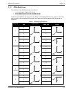
Signal Description
a
a. For information about the SETMARK1OFFSET and TAGGEDMARK1PVA commands, refer to the SPAN on
OEM6 Firmware Reference Manual (OM-20000144). For information about the other commands and logs in
this table, refer to the OEM6 Family Firmware Reference Manual
(OM-20000129).
Event1
(Mark 1)
An input signal for which a pulse greater than 150 ns triggers certain logs to be generated.
Polarity is configurable using the MARKCONTROL command.
PPS
(Pulse Per Second)
A time synchronization output. This is a pulse where the leading edge is synchronized to
receiver calculated GNSS Time. The polarity, period and pulse width can be configured
using PPSCONTROL command.