


26 SPAN-CPT User Manual Rev 8
Chapter 3 SPAN-CPT Operation
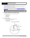
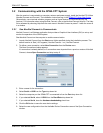
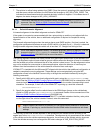
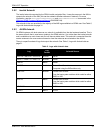
The offset between the antenna phase center and the IMU navigation center must remain constant
and be known accurately. The X, Y and Z positive directions are clearly marked on the SPAN-CPT
enclosure. The SETIMUTOANTOFFSET parameters are in metres:
SETIMUTOANTOFFSET x_offset y_offset z_offset [x_stdev] [y_stdev]
[z_stdev]
The standard deviation fields are optional and the distances are measured from the IMU navigation
center to the antenna phase center.
A typical RTK GNSS solution is accurate to a few centimetres. For the SPAN-CPT system to have
this level of accuracy, the offset must be measured to within a centimetre. Any offset error between
the two systems directly affects the output position. For example, a 10 cm error recording this offset
will result in at least a 10 cm error in the output.
3.4 Real Time Operation
SPAN-CPT operates through the OEM6 command and log interface. Commands and logs specifically
related to SPAN-CPT operation are documented in the SPAN on OEM6 Firmware Reference Manual
(OM-20000144).
Real time operation notes:
• Inertial data does not start until FINESTEERING time status is reached, and therefore, the
SPAN-CPT system does not function unless a GNSS antenna is connected with a clear view of
the sky.
• The inertial solution is computed separately from the GNSS solution. The GNSS solution is
available from the SPAN-CPT system through the GNSS specific logs even without SPAN
running. The integrated GNSS+INS solution is available through special INS logs documented in
the SPAN on OEM6 Firmware Reference Manual
(OM-20000144).
• The IMU solution is available at the maximum rate of output of the SPAN-CPT (100 Hz). Because
of this high data rate, a shorter header format was created. These shorter header logs are
defined with an S (RAWIMUSB rather than RAWIMUB). We recommend using these logs
instead of the standard header logs to save throughput on the COM port.
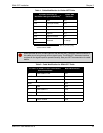
Status of the inertial solution can be monitored using the inertial status field in the INS logs, Table 4,
Inertial Solution Status on page 27.
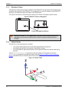
This example assumes a default mounting configuration and shows an -X offset, -Y offset
and +Z offset.
Z Offset
Y Offset
Y Offset
X Offset
Y
Z
Y
X