


18 SPAN-CPT User Manual Rev 8
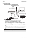
Chapter 2 SPAN-CPT Installation
2.2.7 CAN Bus
The SPAN-CPT has a CAN Bus controller that supports physical layer signals and low level messages
specified in the appropriate sections of the J1939 and ISO11783 standards. Manufacturers can also
create messages specific to their application without violating these standards. To facilitate manufacturer
messages, NovAtel provides an Application Program Interface (API). To obtain information about this
API, contact NovAtel Customer Support.
The CAN Bus port is available on the multi-purpose I/O connector on the SPAN-CPT. See Appendix A,
Technical Specifications on page 48 for information on signals, wiring and pin-out information of the
multi-purpose I/O connector.
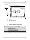
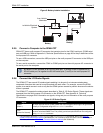
2.2.8 Odometer Connection
The SPAN-CPT provides a wheel sensor input for a Distance Measurement Instrument (DMI) through the
multi-purpose I/O connector. Refer to SPAN-CPT Wheel Sensor on page 30 for additional details.
2.2.8.1 Odometer Requirements
SPAN-CPT is compatible with any wheel sensor meeting the following requirements:
• Input range less than or equal to 45 KHz
• Input duty cycle is symmetric 40%-60%
• Active input voltage is greater than or equal to 2.5 VDC with a maximum input voltage of 50 VDC
• Inactive voltage is less than or equal to 1 VDC
• Input current is approximately 3.5 mA at 5 VDC with a maximum of 5 mA at 50 VDC
• Ensure input current does not exceed 5 mA. There is a current limiting diode that can dissipate
800 mW on the input opto-isolator
• Quadrature, pulse and direction type odometers are compatible
An example of a SPAN-CPT compatible odometer is the CWPTA411 from Kistler (www.kistler.com). A
transducer traditionally fits to the outside of a non-drive wheel. A pulse is then generated from the
transducer which is fed directly to the ODO connector on the IMU cable.
SPAN-CPT powers the odometer. See SPAN-CPT Cable on page 52 for the pin outs of the SPAN-CPT
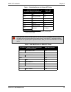
cable. Connect the appropriate pins to the chosen odometer. If the Kistler WPT is chosen, first modify the
cable at the WPT end. The cable modifications are shown in Table 1, Cable Modification for Kistler WPT
Cable and Table 2, Cable Modification for SPAN-CPT Cable on page 19.
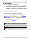
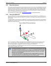
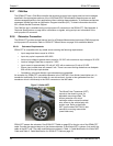
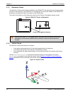
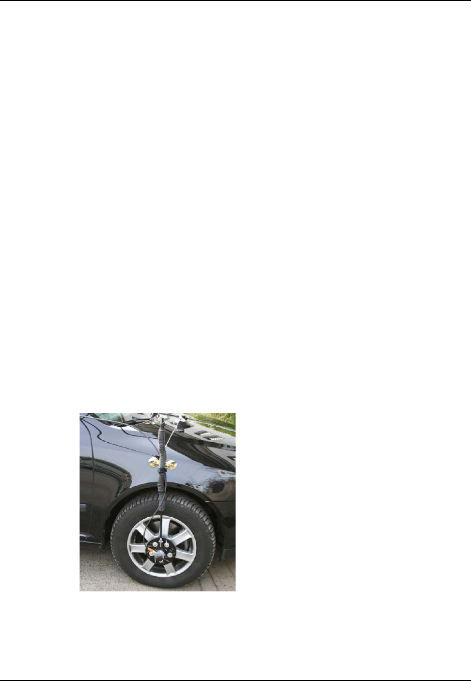
Figure 7: Kistler WPT
The Wheel Pulse Transducer (WPT)
mounts to the wheel lug nuts via
adjustable mounting collets. The
torsion protection rod, which
maintains rotation around the wheel
axis, affixes to the vehicle body with
suction cups. Refer to the Kistler
WPT (part number CWPTA411) user
manual for mounting instructions
(www.kistler.com).