


PHYSICAL INSTALLATION CM9760-SAT 1-5
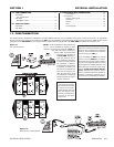
3.5 AUXS
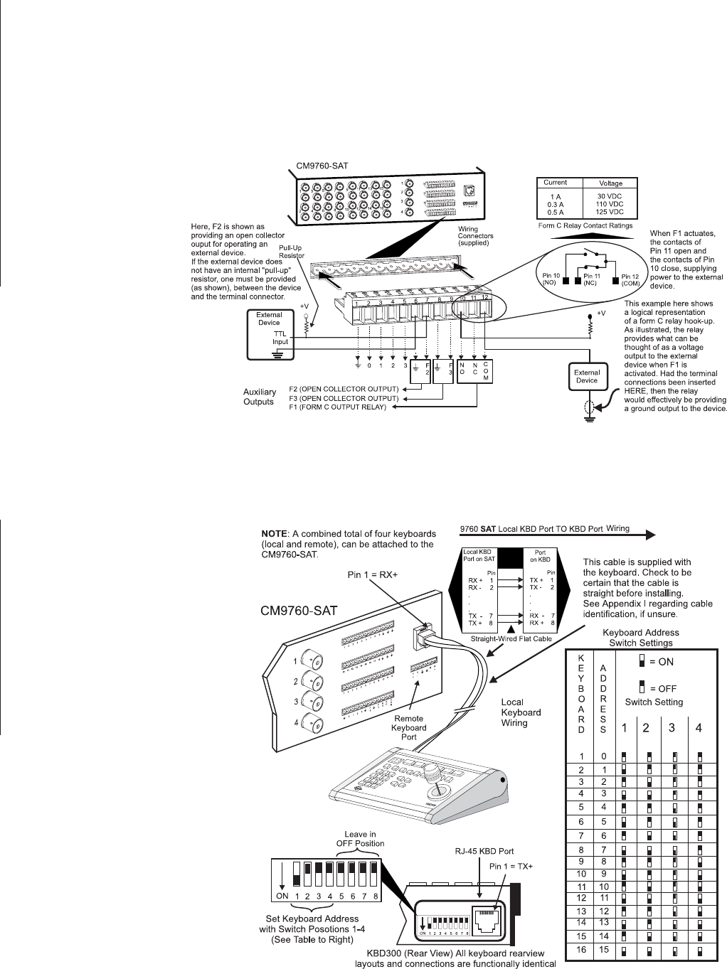
There are three AUX outputs available through the control output wiring terminals located on the rear of the SAT. Aux operation and control are
for local SAT SIDE use only. Aux ouputs cannot be controlled from the 9760-KBD. These outputs are used to operate external devices. Each
output corresponds to a function key (F1-F3) on the KBD200/300/300V keyboard. The outputs can also be programmed to respond automati-
cally to alarms. F1 is a Form C relay wired with a common (COM) and a normally open (N.O.) or normally closed (N.C.) contact. The other two
outputs (F2 and F3) are open collector transistor drivers that drive TTL circuits or low-current relays. If you use an external relay, make sure that
voltage and current requirements are well below maximum ratings. Exceeding specified values can permanently damage the transistors.
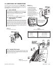
During programming, configure the auxiliary outputs to agree with the type of equipment you are using. Refer to Section 2,
Auxiliaries
Programming Menu-Page 1 of 1.
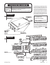
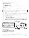
Follow the examples illustrated in
Figure 1-10 for wiring up the F1,
F2 and F3 relay contacts. The in-
structions for wiring the F3 relay
are the same as those illustrated
for F2, if you substitute pins 8 and
9 for pins 6 and 7. When you fin-
ish wiring the auxiliary outputs,
plug the wiring connector into the
control outputs terminal strip.
Figure 1-11
Wiring the Local Keypad Port
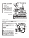
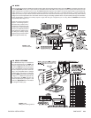
3.6 LOCAL KEYPADS
The KBD200/300 may be connected to
the local keyboard port on the SAT and
used (in conjunction with the local moni-
tor) for local SAT operations and program-
ming. The KBD300V cannot be used with
the local keyboard port as the matrix dis-
play is not compatible with the voltages
supplied there. Connect the keyboard to
the local SAT keyboard port as indicated
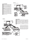
in Figure 1-11. Additional keyboards may
be connected to the SAT unit using the
remote keyboard port (see Figure 1 and
reference Appendix II for information
on wiring the remote port).
Figure 1-10
Aux Connections