


1-2 C1510M-A (2/03) SECTION 1
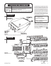
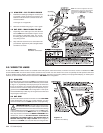
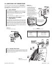
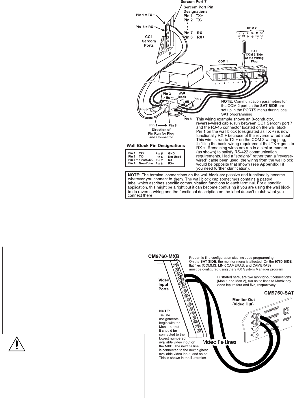
1.1 9760 SIDE – CC1 TO WALL BLOCK
1. Determine the cable type (straight or reverse)* that
is provided or exists on-site that you want to use
between the RJ-45 Sercom connector on the CC1
and the wall block.
*see Figure 5-1 in Appendix I
2. Make the connection using Figure 1-3 as a guide.
1.2 SAT SIDE – WALL BLOCK TO SAT
1. Depending on the cable type used, wire the wall
block-to-SAT connection based on Figure 1-3 and
the included pin designation table. The 12-posi-
tion wiring plug can be removed from the unit for
easy wiring access.
2. Strip and insert each wire to be connected in the
provided slot. Tighten firmly with a straight-slotted
screwdriver as shown.
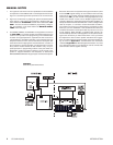
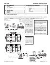
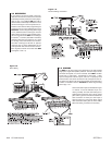
2.0 VIDEO TIE LINES
In order for the SAT to fulfill its function as a Satellite of the 9760 system, video interconnects, in the form of tie lines, must be run between the SAT
and the CM9760-MXB. The tie line–there must be at least one–has several uses. One function is to serve as a pathway for 9760 operators who want
to call up satellite camera displays via their 9760 system keyboards. The other is to provide a pathway for the programmed display (on 9760-system
monitors) of alarm-activated link cameras located on the SAT SIDE of the configuration.
2.1 9760 SIDE
The video tie lines coming from the SAT are connected to avail-
able, video input BNCs on the CM9760-MXB unit (see the NOTE
in Figure 1-4). Specifically note the physical port to which each
tie line is connected. You need this information later, when the
Cameras and Link Cameras configuration files (flat files) are pro-
grammed on the 9760 SIDE of the configuration. These inputs
are treated differently so that they are recognized as tie lines and
not just regular video inputs.
2.2 SAT SIDE
You must also allocate at least one monitor-out on the SAT SIDE
of the configuration to tie line use. In most instances, you also
need one monitor-out for local SAT operation and programming.
IMPORTANT NOTE:
The ratio of tie line to local moni-
tor-out use is under user control, subject to the condi-
tion that at least one tie line exists and that the following
rule for multiple tie line hookup is obeyed: If you use
one
tie line,
it must be connected to the
MON 1
BNC. If you use
two
tie
lines, they must be connected to the
MON 1 and MON 2
BNC
monitor-outs, and so on.
Tie lines must be connected in
sequential, ascending order to the monitor-outs on
the SAT. You may not “skip” around.
Never configure a
monitor-out for
LOCAL
use until all tie lines are configured first.
NOTE: The Comms configuration file in the
MGR program is used to set communication
parameters for the SAT connected to the
Sercom port (see SECTION 2, 3.1 COMMS
Files).
Figure 1-3
Wall Block Connections
Figure 1-4
Video Tie Line Hookup