


4-10 C1510M-A (2/03) SECTION 4
Shortly thereafter (during the time that steps 4 through 7 occur, which are almost concurrent from a user viewpoint ) the System manager’s
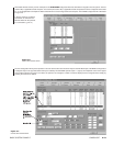
System window will indicate that the video from logical camera 5007 has switched to an alarm monitor. It might look something like this:
9:05:38 16/08/00 Nd:01 SWITCAMMON Camera: 5007 Monitor: 001 Op: 1
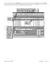
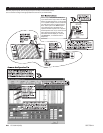
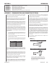
9. At the same time, the AT diagnostic screen’s Monitor box shows that camera display 5007, which utilizes a tie line, is displayed on Mon 1.
The system box (or system error line) is illustrated in Figure 4-2.
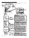
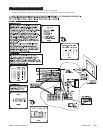
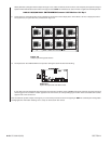
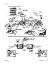
10. The keyboard on the CM9760-KBD for the operator viewing this alarm will show the following:
If more than one alarm happened (with none being reset) the alarm numbers on the 9760KBD LCD screen sequence and cycle among all
alarms triggered. As each alarm number appears on the LCD screen, the corresponding logical number of the associated alarm camera
appears next to the camera icon.
This concludes the system example, which gives you a hint of the processes involved in integrating an SAT into a 9760 System configuration
and highlights how information affecting such a setup can be located in this manual.
Figure 4-3
System Example 9760 LCD Alarm Event
Figure 4-2
Sample System Diagnostic Screen