


3-4 C1510M-A (2/03) SECTION 3
1.5 CONTROLLING AUXILIARIES
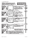
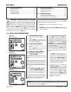
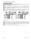
1.5.1 Activating Switcher Auxiliaries, F1-F3
Three function keys (F1-F3) manually control the three auxiliaries that can be connected to the CM9760-SAT. To operate an auxiliary, press an
F1-F3 button. Know how your system is configured and programmed before operating auxiliaries.
• For momentary operation, pressing a key sends a micropulse to the equipment
connected to the auxiliary output.
• For latching operation, pressing a function key is similar to an on/off switch.
• For keyed operation, the auxiliary operates as long as the key is held down.
Even though an auxiliary is programmed to operate when there is an alarm, it can also
be operated manually by pressing the function key.
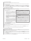
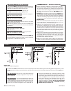
1.5.2 Activating Receiver Auxiliaries, F4 AND F5
With properly equipped and correctly wired receiver auxiliaries, you
can activate as many auxiliaries as allowed by the receiver from a
KBD200 or KBD300/KBD300V keyboard. The F4 key acts as ON and
F5 as OFF for each receiver auxiliary. If a receiver has multiple auxil-
iaries, precede the F4 or F5 key with the appropriate auxiliary number
from the number pad.
Figure 3-13
Activating Receiver Aux’s
Figure 3-12
Activating Switcher Aux’s
2.0 9760-SAT OPERATIONS
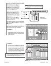
2.1 SELECTING LINK (SATELLITE) CAMERAS
Link cameras connected to a CM9760-SAT are available for viewing by any 9760 operator for which access to the camera has been parti-
tioned. Link camera identification and availability is realized through the configuration of the Link Camera flat file (see Section 2,
3.3 LINK
CAMERAS FILE
). Cameras listed in the Link Cameras file are accessed just as those listed in the Cameras configuration file; namely, by using
the associated logical number entered for each listed camera. The logical number is the call-reference used for keyboard command and
control operations by 9760 keyboard operators to call-up satellite (link cameras).
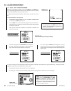
2.1.1 Calling Link Cameras
To call a specific link camera to a 9760 system monitor from a 9760 keyboard, do the following:
a. Be sure the monitor you wish to use to view the display is available and selected.
b. Enter the logical number of the link camera that you wish to call into the keypad of the 9760-KBD and press the CAM button. The referenced
camera display should appear on the monitor.
NOTE:
You can call up all link cameras attached to all SATs within a node from the same operator position, one at a time, if you want. Access to
the camera called must have been granted beforehand (see
Section 2
,
3.3 Link Cameras File
).
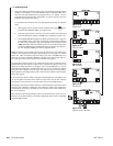
2.1.2 Cycling Through Link Cameras
Link camera entries can also be accessed by cycling through the available camera field from the 9760 keyboard by pressing the FWD or BWD
buttons.
IMPORTANT:
Any time another link camera is called by the same operator to a different monitor on the
9760 SIDE
of a configura-
tion without releasing control of a previously called camera, the next available tie line is utilized. Conceivably, a single operator could
quickly lock up all available tie lines.