


BASIC SYSTEM EXAMPLE CM9760-SAT 4-1
SECTION 4 SYSTEM AND MULTIPLIEXER EXAMPLE
1.0 SYSTEM EXAMPLE
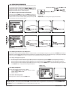
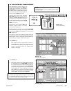
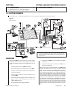
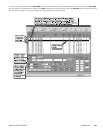
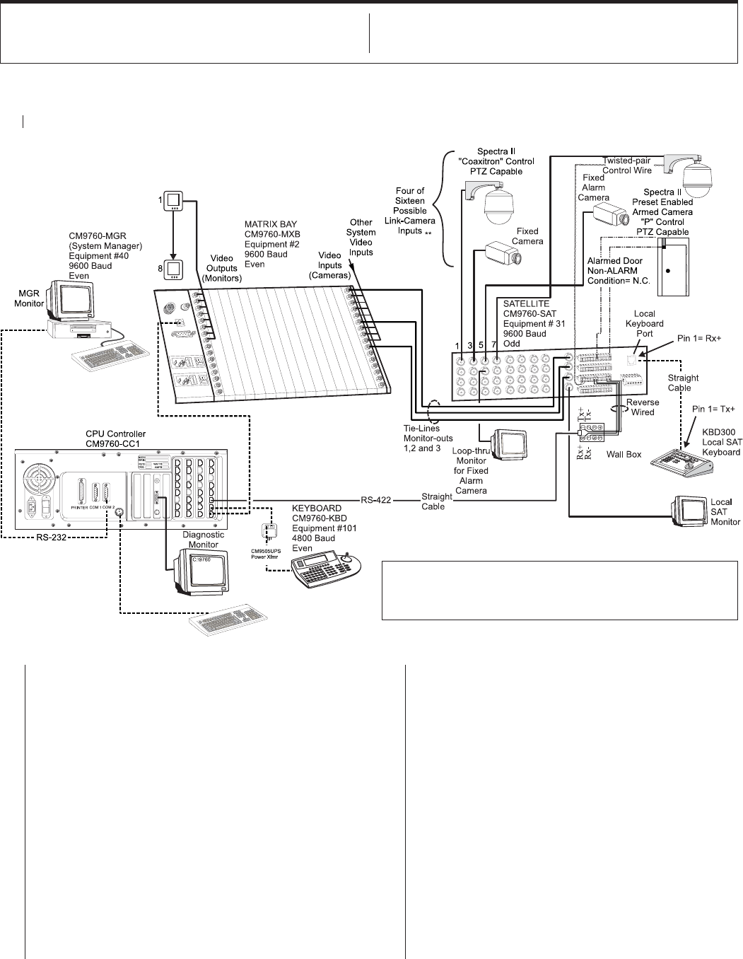
We shall use Figure 4-1 to highlight the processes involved in integrating a CM9760-SAT into a 9760 environment.
Figure 4-1
System Example
OVERVIEW
Integrating an SAT into a 9760 system occurs in two stages:
(1) hooking it up (items 1-6 below), and (2) programming it (items
7 and 8). The list below is based on the diagram above. It is as
follows:
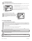
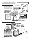
1. Attach a keyboard to the local SAT keyboard port.
2. Attach a local monitor to the monitor-out port on the SAT.
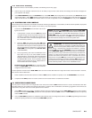
3. Establish a communication link between the CM9760-CC1
and the CM9760-SAT.
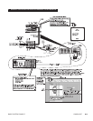
4. Run link-cameras (satellites) to the video input BNCs on the
rear of the SAT.
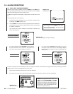
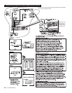
5. Run tie lines from the appropriate monitor-out BNCs on the
SAT to available video input BNCs on the rear of the
CM9760-MXB (matrix bay).
6. Attach and configure alarm inputs and wiring.
7. Program the local SAT menus to correspond to your physi-
cal hook-up.
8. Program the 9760 System to incorporate the SAT unit into
the system environment.
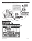
We shall not engage in detailed discussions of non-SAT related
matters. We will discuss, in turn, each of the above numbered
items. For each, we shall (1) isolate that portion of Figure 4-1
under discussion (2) discuss any and all applicable programming
menus associated with that item, and (3) add other pertinent re-
marks and/or give appropriate manual references where appli-
cable. Please note that items 7 and 8 (software) are not discussed
as individual items, separate from other items in the installation
process, but are considered at the time each physical item (1 through
6) is discussed. In actual practice, programming is not necessar-
ily performed concurrent with physical setup. We do so here be-
cause our purpose is to inform, to illustrate the close relationship
between the device and the program that controls it and, in the
process, perhaps point out how best this manual can be put to
use.
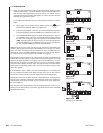
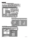
** For link-camera inputs 1, 3, 5, and 7 (SAT SIDE), we assign (for 9760
purposes) corresponding logical numbers of 5001, 5003, 5005 and 5007.
We limit our discussion to these specific inputs as we discuss the system
illustrated above.
1.0 SYSTEM EXAMPLE ........................................................ 4-1
1.1 OPERATION OF THE SYSTEM EXAMPLE ............... 4-9
2.0 MULTIPLEXER EXAMPLES.........................................4-11