


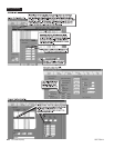
4-12 C1510M-A (2/03) SECTION 4
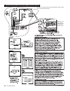
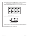
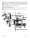
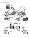
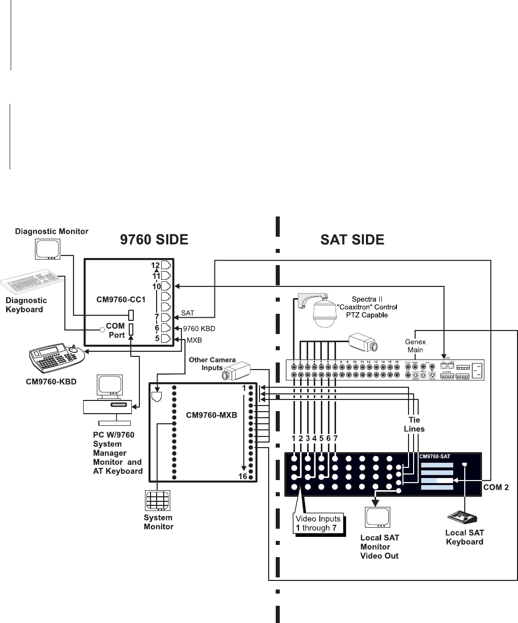
Figure 4-4 illustrates the minimum physical connections using the pieces of equipment required for camera control through the Genex. Specifi-
cally illustrated are the coaxitron, camera-related connections necessary for operators on both sides of the configuration to have control-
access to Genex camera input 1. The SAT SIDE operator has access by entering 1 on his keypad and pressing the CAM button; the 9760 SIDE
operator has equal access and control by calling camera 5001 to his available monitor. Other than Genex-looped inputs, the SAT operator can
also control direct “SAT-connected” cameras that use Pelco “P” type protocol (not run through the Genex, but connected directly to other SAT
video inputs; control wiring must also be run). At the same time, operators on the 9760 SIDE can view and control all SAT connected cameras
that are properly configured.
EXAMPLE TWO: MUX CONTROL IN A 9760-SAT SYSTEM ENVIRONMENT
Part I - Mux Control from the 9760 SIDE
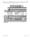
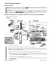
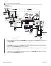
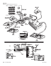
Note that the Genex control line in Figure 4-4 connected to the COM “IN” port is connected to Sercom input port 10 on the CC1. That’s one
requirement for enabling MUX control from the 9760 SIDE.
To fully enable MUX control, Figure 4-4 needs to be altered slightly. That change is reflected in Figure 4-5. It involves the connection of a video
cable between the MUX main output on the Genex and an available BNC video input on the CM9760-MXB. We choose BNC input 11.
Figure 4-5.
9760-SIDE Mux Control