


5-2 C1510M-A (2/03) SECTION 5
APPENDIX II – REMOTE KEYPAD CONNECTION
Four keyboards, total, may be attached to the CM9760-SAT. This includes concurrent connection to the local and the remote keyboard ports.
The local keyboard port was discussed previously. The remote keyboard port is illustrated and discussed here.
Any of the keyboard models used with the CM9760-SAT may be wired to the remote port. All keyboards, except the KBD300V, may be attached
to the local port. This is because power requirements for the LCD screen on the KBD300V are not available at the local port. The keyboard
requires a separate transformer for this purpose. In fact, any keyboard attached to the remote port requires an external power source, as no
power is provided at that port.
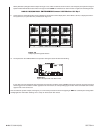
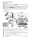
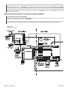
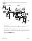
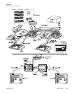
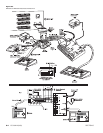
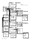
On the next two pages are examples of wiring keyboards to the remote port. The first shows two KBD300s wired to the remote port. The second
shows a KBD300 and a KBD300V attached to the remote port.
NOTE:
You can connect only one keyboard (KBD200 and KBD300) at time to the Local Keyboard port. You cannot daisy-chain from that
port. Additional keyboards may be added by parallel wiring from existing wall blocks or by using the com out port on the KBD300V
interface (see Figure 5-3). If you use more than one keyboard, each must have a different address (see Figure 1-11).
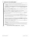
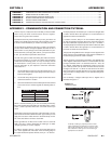
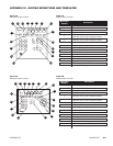
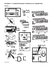
Sometimes, a physical disparity exists between two connecting devices such that the wiring geometry you start with at one end is different from
that at the other end. Nevertheless, the wiring relationships stated in point 3 must be satisfied. An example of this occurs in the manual when
connecting a CC1 sercom port to a COM 2 port on the CM9760-SAT (see Section 1, 1.1 and 1.2).
The wiring scenario utilized a wall block, which is part of a “wiring kit”, that can be obtained from Pelco
.
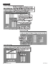
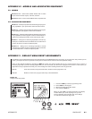
NOTE:
You should not get confused by the pasted-in wiring label in the cap of the wiring block that you sometimes see. Although it has
named signal functions for each terminal pin, you must remember that this is a passive device and the actual signal that appears on any
terminal is the one that you put there.
You should keep the following in mind:
1. Plan the wiring for each run ahead of time. Be surprised if it doesn’t work.
2. Verify any manual instructions that specify attachment of a certain cable “type”. Check to be sure the right cable is packed and that the
instructions given don’t run contrary to the previously stated connection rules for signal interfaces.