


BASIC SYSTEM EXAMPLE CM9760-SAT 4-9
1.1 OPERATION OF THE SYSTEM EXAMPLE
That concludes the hook-up and programming of our system example. Once the system to which the SAT is attached is operational, the
following items remain to be configured (in operational mode) before alarm operation is totally enabled:
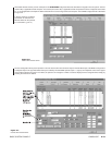
1. On the SAT SIDE, we must still define preset 21. If an alarm triggered before we created the preset, the designated camera input display
( #7) would appear on the local monitor, but the display might be something other than the preset position view that we want.
2. On the 9760 SIDE, we must ARM all defined alarms that we want to see from our keyboard position. ARMing is done from the 9760
keyboard position. In the real world, this would more than likely be taken care of with a Macro that executed whenever the operator logged
onto the system. If an alarm occurred on the SAT SIDE before the alarm was ARMed on the 9760 SIDE, the 9760 SIDE would have
no idea that an alarm occurred.
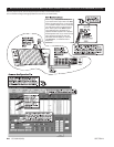
To accomplish (1), follow the instructions in Section 2,
2.1 Programming Presets
and program preset 21 for the alarm-input camera (input 7)
for the system example. A preset label can also be created, if you want.
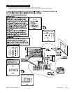
To accomplish (2), the 9760 keyboard is used to ARM the alarm. The logical number (100) for defined alarm (0001) is used to ARM the alarm.
Follow the instructions in Section 3,
3.2 9760-SAT Alarm Response
on how to ARM an alarm from the 9760 keyboard.
NOTE:
Alarm response by operators on the
9760 SIDE
and the
SAT SIDE
are independent of each other, once an alarm condition is
sensed. That is, clearing a triggered alarm on one side of the configuration has no effect on the other side.
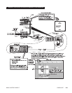
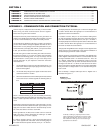
The following is a relatively straightforward time-line of the events that unfold when the alarm-wired door is opened on the SAT SIDE of the
configuration, triggering an alarm event.
1. The door opens, causing the N.C. contacts to open, which signals an alarm condition on the SAT SIDE of the configuration.
2. The alarm overrides any local operator actions in progress and, because of the SAT Alarms file settings, the local monitor display (MON
4) switches to the display input from video input # 7. That display appears on the local monitor. The status sequence indicator on the local
monitor shows an “A” to indicate the alarm condition.
3. In conjunction with (2), the camera for this video input is already at or is in the process of traveling toward alarm preset position 21.
4. The system alarm notification number (0001), entered in the local Alarm menu is sent to the 9760 SIDE of the configuration. Even if the
local SAT operator were to ACK and clear the alarm at this time, it would not affect alarm notification to the system. Once an alarm
occurs, that alarm information is immediately passed on to the 9760 SIDE of the configuration and nothing the local SAT operator can
do will prevent system notification if the menus are so configured.
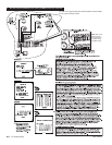
5. In response to alarm notification from the SAT unit, the system (per instructions in the Alarm configuration file) asks the SAT to place the
video from logical link camera 5007 on the first available tie line.
6. The SAT’s response is to place video input 7 (logical 5007) on an available tie-line.
7. On the 9760 SIDE, the received video is placed on an available alarm monitor (previously assigned) for the operator on that keyboard
position via the Comms file. The alarm display parameters are governed by the alarm mode chosen In the System configuration file.
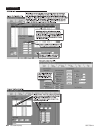
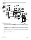
8. On the 9760 SIDE, the System Window (in the 9760-MGR, or System Manager program) indicates the triggering of the alarm on the
SAT SIDE by displaying a line similar to the following:
09:05:38 16/08/00 Nd:01 ALARM 0001 TRIGGER SAT Alarm Op:01 Pr:09