


79
Network Unit
OWNER’S MANUAL
Appendix
ENGLISH
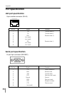
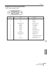
Computer Input port specification
Pin No. Signal Function
1R R input
2G G input
3B B input
4 MONITOR ID2 MONITOR ID2
5 GND(H) Ground(Horiz.)
6 GND(R) Ground(R)
7 GND(G) Ground(G)
8 GND(B) Ground(B)
9 +5V 5V Power Supply
10 GND(V) Ground(Vert.)
11 MONITOR ID0 MONITOR ID0
12 DDC DATA DDC Data
13 H Horizontal Signal Input
14 V Vertical Signal Input
15 DDC CLK DDC Clock
5
1
2
34
10
9 678
15
14
13
11
12
HDB 15-pin connector (VGA)