


&RQQHFWLQJ\RXUV\VWHP
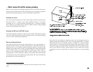
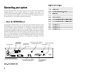
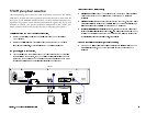
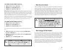
The following information is provided to help you set up and connect the Headend
Satellite Receiver to the satellite antenna, TV monitor, and other A/V
(Audio/Video) headend equipment. The accompanying figure shows receiver rear
panel connections for the NTSC receivers base version. For equipment intercon-
nection details, see “TV & RF plus optional connections”.
…
$ERXWWKH(;3$16,21SRUW
The Headend Satellite Receiver can be operated and monitored remotely via the
EXPANSION port when connected to a PC workstation or data terminal. Remote
receiver operation requires installation of a PC/data communications program.
Note that certain program settings may vary, depending on the type of worksta-
tion/terminal equipment being used. Data interface cables connected between the
Headend Satellite Receiver and some customer equipment may require a unique
pin-out for proper operation via the EXPANSION port (DB-25 female connector).
For port pin-out information, see the accompanying table. Note that only those
EXPANSION port pins used are shown (i.e., all other pins are unused, or are not
required for normal operation).
LNB POWER SW.
TO PC/WORKSTATION
OR DATA TERMINAL
(OPTIONAL)
TO SATELLITE ANTENNA
STEREO/MONO
AUDIO SELECT SW.AC POWER SOCKET
TO L/R BALANCED AUDIO INPUT
TERMINAL BLOCK (CABLE HEADEND)
L/R BALANCED
AUDIO OUTPUT
LEVEL CONTROLS
TO VIDEO INPUT (CABLE HEADEND)
OR EXTERNAL MODULATOR
TO AUDIO INPUT (CABLE HEADEND)
OR EXTERNAL MODULATOR
803-297
Scientific
Atlanta
Satellite Television Networks
SATELLITE
LNB PWR
+13/+19V 500mA MAX
AC IN 100V-240V ~AC
50/60Hz 1.4A MAX
AUDIO
RL
EXPANSION PORT
VIDEO
ON OFF
LNB PWR
This apparatus
must be earthed
Ω
Ω