55
E
[Advanced operation] Control command table
How to read the command table
Command: Command eld (See page 53.)
Direction: W When the “Parameter” is set in the parameter eld (see page 53.), the command functions as described
under “Control/Response Contents”.
R The returned value indicated under “Reply” can be obtained by setting “????” or “
?” in the
parameter field. (see page 53.).
Parameter: Parameter eld (See page 53.)
Reply: Response (Returned value)
TIPS
• The following commands cannot be used in standby mode.
TPEN, ASNC, CLCK, PHSE, HPOS, VPOS, HSIZ, VSIZ, HRES, VRES, ARST, CPTU, AGIN, TOMD, PXCK, PXSL, RESO,
RSET, MUTE
Power control/Input mode selection
Function
Command Direction
Parameter Reply Control/Response contents
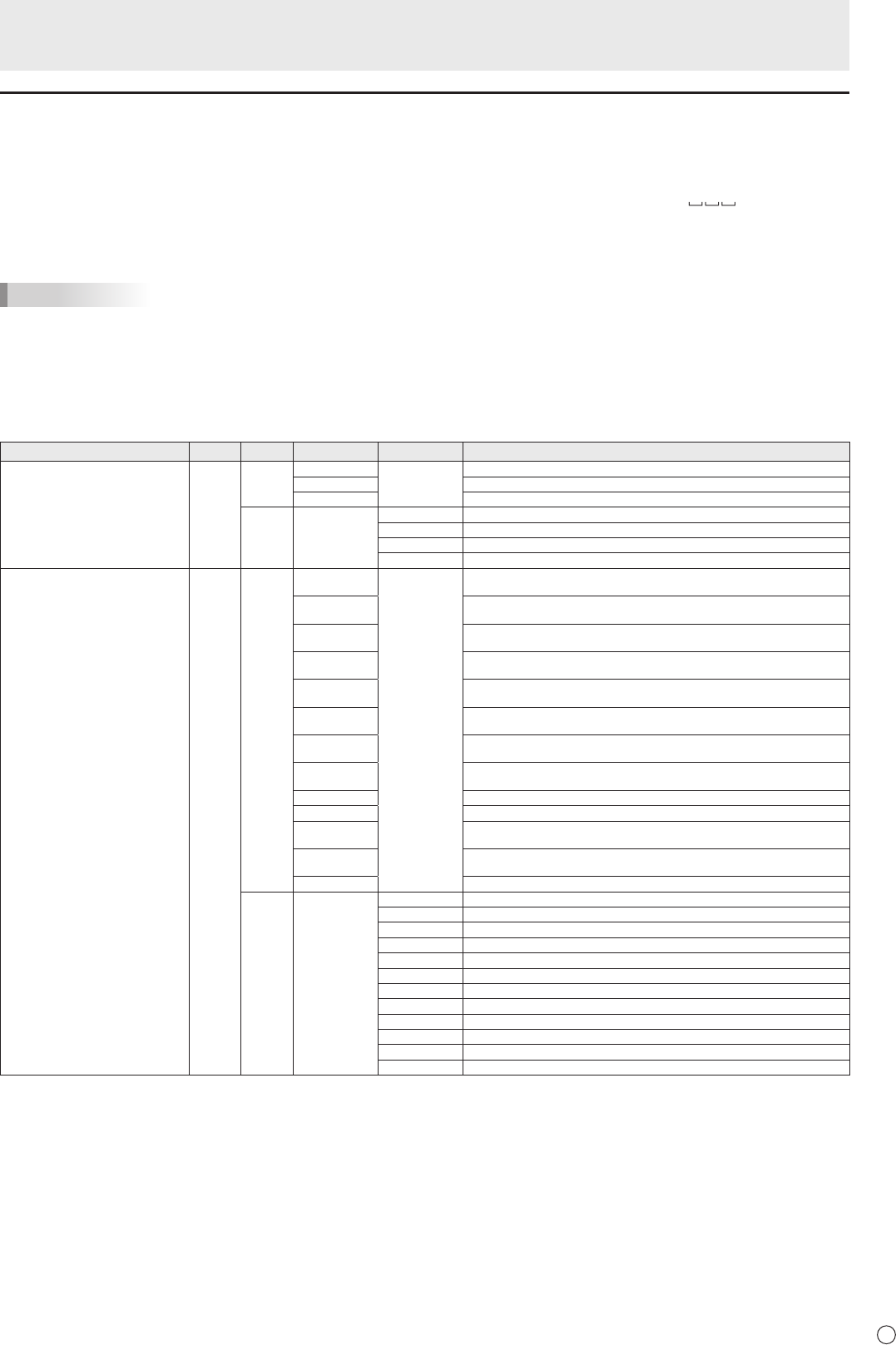
POWER CONTROL POWR W 0
Switches to standby mode.
1 Enters the power ON state.
99 Switches to whiteboard standby mode.
R 0 Standby mode
1 Normal mode
2 Input signal waiting mode
99 Whiteboard standby mode.
INPUT MODE SELECTION INPS W 0 Toggle change for input mode. Terminals not selected in INPUT SELECT cannot be
selected.
2 D-SUB1[RGB]
“ERR” when other than RGB is selected for D-SUB1 of INPUT SELECT.
3 D-SUB1[COMPONENT]
“ERR” when other than COMPONENT is selected for D-SUB1 of INPUT SELECT.
4 D-SUB1[VIDEO]
“ERR” when other than VIDEO is selected for D-SUB1 of INPUT SELECT.
9 HDMI1[AV]
“ERR” when PC is selected for HDMI1 of INPUT SELECT.
10 HDMI1[PC]
“ERR” when AV is selected for HDMI1 of INPUT SELECT.
12 HDMI2[AV]
“ERR” when PC is selected for HDMI2 of INPUT SELECT.
13 HDMI2[PC]
“ERR” when AV is selected for HDMI2 of INPUT SELECT.
14 DisplayPort
16 D-SUB2
17 HDMI3[AV]
“ERR” when PC is selected for HDMI3 of INPUT SELECT.
18 HDMI3[PC]
“ERR” when AV is selected for HDMI3 of INPUT SELECT.
19 WHITEBOARD
R 2 D-SUB1[RGB]
3 D-SUB1[COMPONENT]
4 D-SUB1[VIDEO]
9 HDMI1[AV]
10 HDMI1[PC]
12 HDMI2[AV]
13 HDMI2[PC]
14 DisplayPort
16 D-SUB2
17 HDMI3[AV]
18 HDMI3[PC]
19 WHITEBOARD
Controlling the Monitor with a PC (LAN)


