


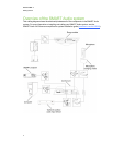


Physical components
YourSMARTAudio system includes the following:
l Control unit and its power supply
l Microphone, sleeve and lanyard
l Microphone charging cradle and its power supply
l Ceiling-mounted room module, infraredsensor and amplifier
l Eitherfour ceiling-mounted speakers or fourwall-mounted speakers
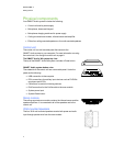
Control unit
The control unit is a wall-mounted panel that connects the
SMARTAudio system to your computer. For more information onusing
the control unit, see Using the control unit on page 9.
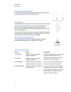
The SMARTAudio 340 system top view
The top of the SMARTAudio 340 system includes a Power button.
SMARTAudio system bottom view
The underside of the control unit has aremovable panel. Under the
panel are the following:
l
USB connection to the computer
l
RCA connections for auxiliary input devices such asDVD/Blu-
rayplayers and VCRs
l
Connectors for assistive listening devices
l
RJ45 connection for the Cat 5e cable to the room module
l
System power input
l
System Reset button
Aux In
Out
To RM
19 VDC
RESE T
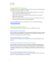
Room module
The ceiling-mounted room module contains the infrared sensor and the
speaker amplifiers. It is connected to all of the speakers and to the
control unit.
PAGING
INPU T
6-12VDC
INPUT
NINI
TO C U
RELAY
OUTPUT
N.C. N.O.COM
SMART Bus
Expansion
Sensors
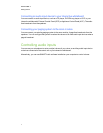
Wall-mounted speakers
The four 30 W wall-mounted speakers receive both power and audio
input through speaker wire from the room module.
C HA PTER 1
Gettingstarted
4