


Installing the Equipment
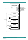
Reference Guide: TT128x High Definition Professional Receiver/Decoder Page 2-15
ST.RE.E10141.5
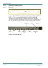
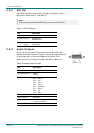
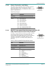
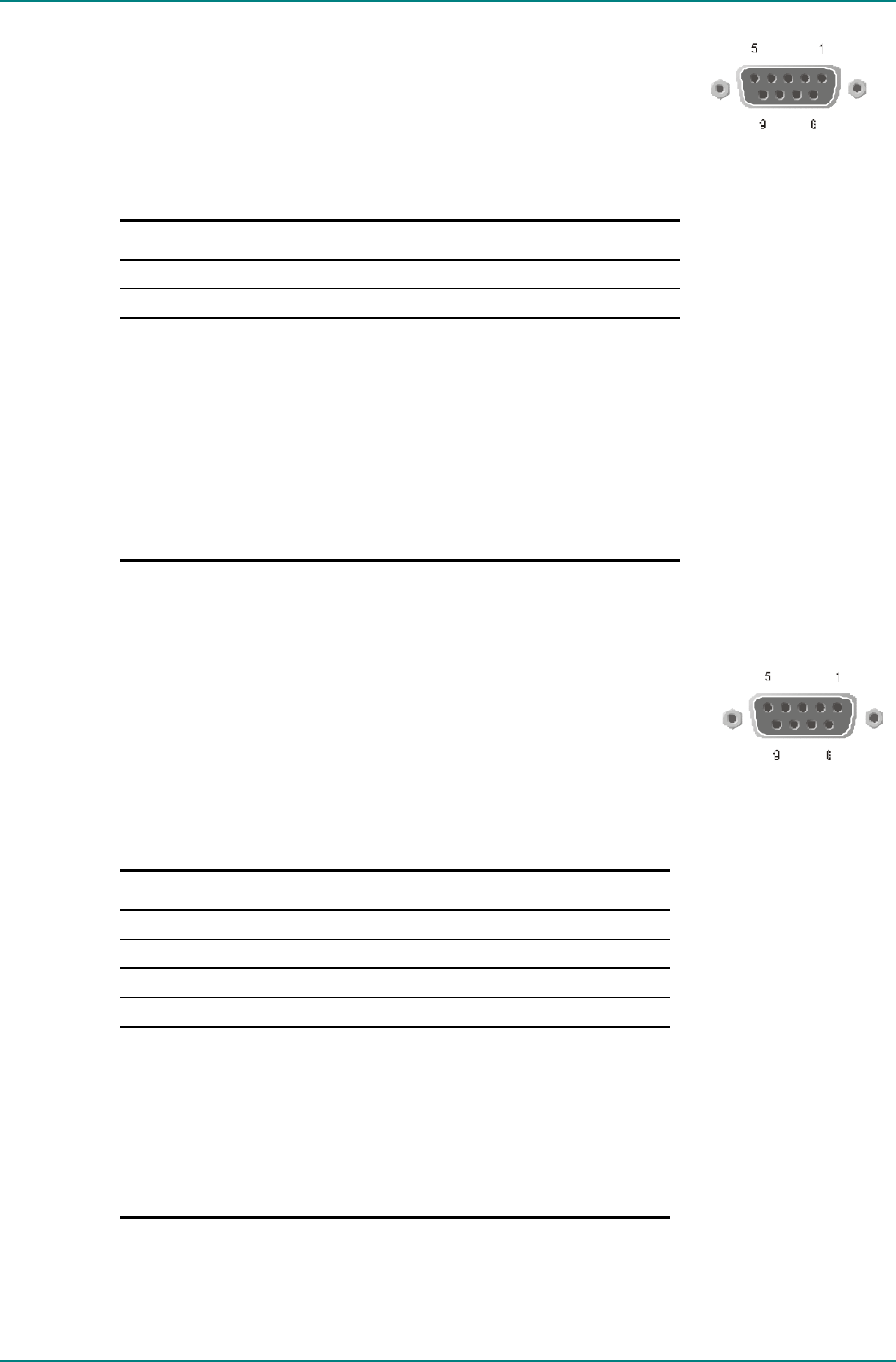
2.8.8 Alarm Connector and Relay
The alarm relay connector has a summary and four
general purpose relays. The summary relay is
activated whenever the unit detects an alarm, or the
power is switched off.
Table 2.9: Alarm Connector
Item Specification
Connector type 9-way, D-type, Female for the summary alarm relay
Connector designation ALARM RELAY
Pin-outs Pin 1 Relay 2, Normally open
Pin 2 Relay 3, Normally open
Pin 3 Relay 4, Normally closed
Pin 4 Relay 1, common pin
Pin 5 Relay 5, Normally closed
Pin 6 Relays 2 and 3, common pin
Pin 7 Relays 4 and 5, common pin
Pin 8 Relay 1, Normally Closed (Open on Alarm)
Pin 9 Relay 1, Normally Open (Closed on Alarm)
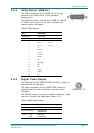
2.8.9 RS-232 Low-speed Asynchronous and RS-422
High-speed Synchronous Data Outputs
A 9-way, D-type female connector provides a shared
simultaneous asynchronous low-speed data and
synchronous high-speed data serial communications
interface. The status of the data output on this
connector is given in the Data menus (Menus 3.4
and 3.5).
Table 2.10: RS-232 Low-speed/RS-422 High-speed Data Connector
Item Specification
Connector type 9-way, D-type, Female
Connector designation RS232/RS422 Data Out
Standards RS-232 DATA/RS-422 DATA
Configuration DCE
Pin-outs
Pin 1 CLK (RS-422)
Pin 2 Receive Data Output (RxD) (RS-232)
Pin 3 Not Used
Pin 4 Not Used
Pin 5 Ground (RS-232)
Pin 6 CLK (inverted) (RS-422)
Pin 7 Not used
Pin 8 DATA (RS-422)
Pin 9 DATA (inverted) (RS-422)
A
LARM RELA
Y
RS232/RS422 Data Out