


Options
Reference Guide: TT128x High Definition Professional Receiver/Decoder Page 6-3
ST.RE.E10141.5
6.1 Hardware Enabled Options
These options require extra hardware to be fitted to the unit. Contact the
Customer Services Helpdesk for details (see Preliminary Pages).
6.2 QPSK Input Card (TT1280/HWO/QPSK)
6.2.1 General
The QPSK Input Card supports QPSK demodulation for Satellite Receivers
with two L-band inputs.
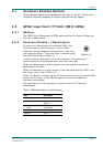
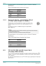
6.2.2 Connector Details - L-Band Inputs
Connect the L-band output of a suitable LNB to the
F-type connector either directly or via a suitable
attenuator giving adequate consideration to lightning
and surge protection. The active input is chosen using
the Input Status Menu (Menu 2).
In most cases an attenuator will not be required. The following list
summarises the circumstances when one should be used.
When the desired input level is greater than the specified maximum
permissible (-25 dBm).
When the downlead is a short length of low-loss cable and the LNB in use
has a poor return loss (7 dB min).
When the Receiver is receiving one of many carriers in a multi-carrier FDM
system and the level of the wanted signal is close to the specified
maximum permissible.
The specification for this connector is given in Annex B, Technical
Specification.
Table 6.1: QPSK Satellite Receiver (L-band) Connector
Input Specification
Connector Type F-type, Female
Connector designation
QPSK IN 1
QPSK IN 2
Pin: Centre
Shield
RF Input
Ground/Chassis
LNB Supply Refer to the next caution box
Impedance 75 Ω
QPSK IN 1/2