


D
NO.
WORDS
DESCRIPTION
INSTRUCTION BIT CODE
MNEMONIC
D
D
D
D
D
D
B
D
D
K
TMS320C25
SPRS010B — MAY 1987 — REVISED NOVEMBER 1990
POST OFFICE BOX 1443 • HOUSTON, TEXAS 77001
16
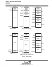
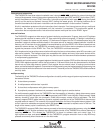
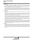
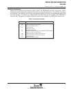
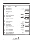
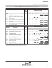
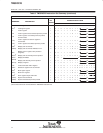
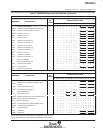
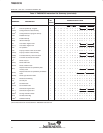
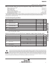
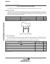
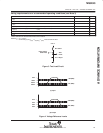
Table 3. TMS320C25 Instruction Set Summary (concluded)
CONTROL INSTRUCTIONS
15 14 13 12 11 10 9 8 7 6 5 4 3 2 1 0
BIT
†
Test bit 1 1 0 0 1 I
BITT
†
Test bit specified by T register 1 0 1010111I
CNFD
†
Configure block as data memory 1 1 100111000000100
CNFP
†
Configure block as program memory 1 1 100111000000101
DINT Disable interrupt 1 1 100111000000001
EINT Enable interrupt 1 1 100111000000000
IDLE
†
Idle until interrupt 1 1 100111000011111
LST Load status register STO 1 0 1010000I
LST1
†
Load status register ST1 1 0 1010001I
NOP No operation 1 0 101010100000000
POP Pop top of stack to low accumulator 1 1 100111000011101
POPD
†
Pop top of stack to data memory 1 0 1111010I
PSHD
†
Push data memory value onto stack 1 0 1010100I
PUSH Push low accumulator onto stack 1 1 100111000011100
RC
‡
Reset carry bit 1 1 100111000110000
RHM
‡
Reset hold mode 1 1 100111000111000
ROVM Reset overflow mode 1 1 100111000000010
RPT
†
Repeat instruction as specified by data
memory value
1
0 1001011I
RPTK
†
Repeat instruction as specified by immediate
value
1
1 1001011
RSXM
†
Reset sign-extension mode 1 1 100111000000110
RTC
‡
Reset test/control flag 1 1 100111000110010
SC
‡
Set carry bit 1 1 100111000110001
SHM
‡
Set hold mode 1 1 100111000111001
SOVM Set overflow mode 1 1 100111000000011
SST Store status register ST0 1 0 1111000I
SST1
†
Store status register ST1 1 0 1111001I
SSXM
†
Set sign-extension mode 1 1 100111000000111
STC
‡
Set test/control flag 1 1 100111000110011
TRAP
†
Software interrupt 1 1 1 0 0 1 1 1 0 0 0 0 1 1 1 1 0
†
These instructions are not included in the TMS320C1x instruction set.
‡
These instructions are not included in the TMS32020 instruction set.