


TMS320C25-50
SPRS010B — MAY 1987 — REVISED NOVEMBER 1990
POST OFFICE BOX 1443 • HOUSTON, TEXAS 77001
35
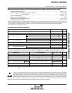
CLOCK CHARACTERISTICS AND TIMING
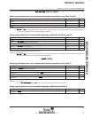
The TMS320C25-50 can use either its internal oscillator or an external frequency source for a clock.
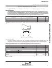
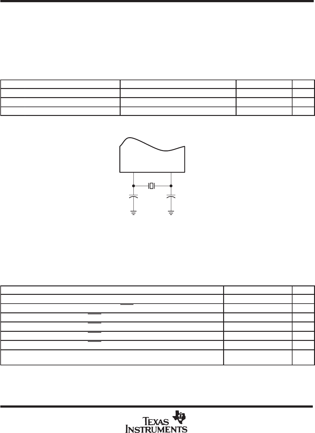
internal clock option
The internal oscillator is enabled by connecting a crystal across X1 and X2, CLKIN. The frequency of CLKOUT1
is one-fourth the crystal fundamental frequency. The crystal should be in either fundamental or overtone mode,
and parallel resonant, with an effective series resistance of 30 Ω, a power dissipation of 1 mW, and be specified
at a load capacitance of 20 pF. Note that overtone crystals require an additional tuned LC circuit.
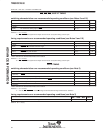
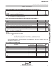
PARAMETER TEST CONDITIONS MIN TYP
†
MAX UNIT
f
x
Input clock frequency T
A
= 0°C to 70°C 6.7 51.2 MHz
f
sx
Serial port frequency T
A
= 0°C to 70°C 0 6.4 MHz
C1, C2 T
A
= 0°C to 70°C 10 pF
†
The serial port was tested at a minimum frequency of 1.25 MHz. However, the serial port was fully static but will properly function down to
f
sx
= 0 Hz.
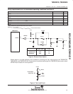
X2/CLKIN
C2C1
X1
Crystal
Figure 6. Internal Clock Option
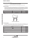
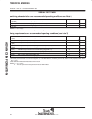
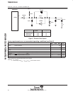
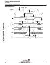
external clock option
An external frequency source can be used by injecting the frequency directly into X2/CLK, with X1 left
unconnected. The external frequency injected must conform to specifications listed in the following table.
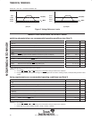
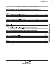
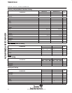
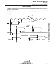
switching characteristics over recommended operating conditions (see Note 3)
MIN NOM MAX UNIT
t
c(C)
CLKOUT1, CLKOUT2 cycle time 78.13 597 ns
t
d(CIH-C)
CLKIN high to CLKOUT1, CLKOUT2, STRB high, low 12 27 ns
t
f(C)
CLKOUT1, CLKOUT2, STRB fall time 4 ns
t
r(C)
CLKOUT1, CLKOUT2, STRB rise time 4 ns
t
w(CL)
CLKOUT1, CLKOUT2, STRB low pulse duration 2Q – 7 2Q + 3 ns
t
w(CH)
CLKOUT1, CLKOUT2, STRB high pulse duration 2Q – 3 2Q + 7 ns
t
d(C1-C2)
CLKOUT1 high to CLKOUT2 low,
CLKOUT2 high to CLKOUT1 high, etc.
Q – 6 Q + 2 ns
NOTE 3: Q = 1/4 t
c(C)
ADVANCE INFORMATION