


TMS320C25
TMS320C25-50
SPRS010B — MAY 1987 — REVISED NOVEMBER 1990
POST OFFICE BOX 1443 • HOUSTON, TEXAS 77001
56
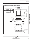
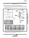
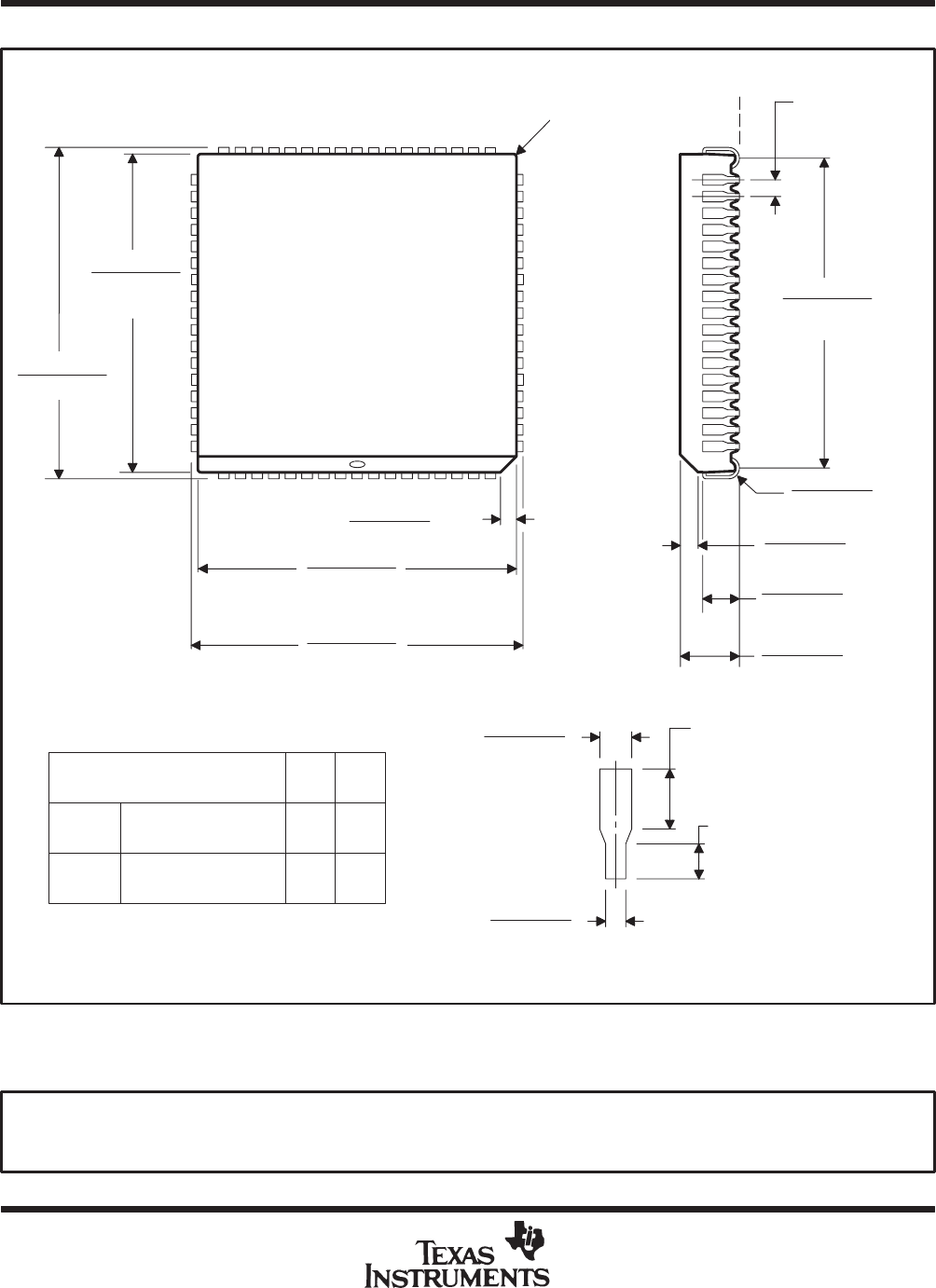
68-lead plastic leaded chip carrier package (TMS320C25 and TMS320C25-50)
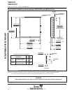
ALL LINEAR DIMENSIONS ARE IN MILLIMETERS AND PARENTHETICALLY IN INCHES
25,27 (0.995)
25,02 (0.985)
24,33 (0.956)
24,13 (0.950)
0,81 (0.032)
0,66 (0.026)
0,51 (0.020)
0,36 (0.014)
1,52 (0.060)
Min
0,64 (0.025)
Min
4,50 (0.177)
4,24 (0.167)
2,79 (0.110)
2,41 (0.095)
1,27 (0.050) T.P.
(see Note B)
0,25 (0.010) R Max
3 Places
(see Note A)
25,27 (0.995)
25,02 (0.985)
24,33 (0.956)
24,13 (0.950)
(see Note A)
23,62 (0.930)
23,11 (0.910)
(At Seating Plane)
1,35 (0.053)
1,19 (0.047)
R
θJA
Junction-to-free-air
thermal resistance
46 °C/W
R
θJC
Junction-to-case
thermal resistance
11 °C/W
PARAMETER MAX UNIT
Thermal Resistance Characteristics
Seating
Plane
Lead Detail
1,22 (0.048)
1,07 (0.042)
× 45°
× 45°
0,94 (0.037)
0,69 (0.027)
R
NOTES: A. Centerline of center pin, each side, is within 0,10 (0.004) of package centerline as determined by this dimension.
B. Location of each pin is within 0,127 (0.005) of true position with respect to center pin on each side.
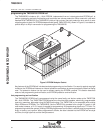
WARNING
When reflow soldering is required, refer to page 54 for special handling instructions.
ADVANCE INFORMATION