


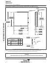
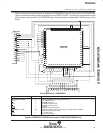
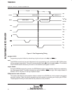
ALL LINEAR DIMENSIONS ARE IN MILLIMETERS AND PARENTHETICALLY IN INCHES
R
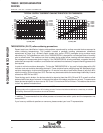
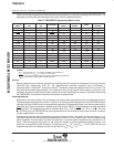
θJA
Junction-to-free-air
thermal resistance
49 °C/W
R
θJC
Junction-to-case
thermal resistance
8 °C/W
PARAMETER
MAX UNIT
Thermal Resistance Characteristics
(see Note 1)
A
(see Note 2)
B
B
A
(see Note 2)
1,02 (0.040) × 45°
0,64 (0.025)
R
Max
3 Places
1,27 (0.050) Typ
(see Note 3)
C
(At Seating
Plane)
3,05 (0.120)
2,29 (0.090)
4,57 (0.180)
3,94 (0.155)
3,55 (0.140)
3,05 (0.120)
0,51 (0.020)
0,36 (0.014)
0,81 (0.032)
0,66 (0.026)
1,016 (0.040) Min
Ref
Seating
Plane
(see
Note
4)
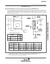
JEDEC
OUTLINE
NO. OF
TERMINALS
TMS320E25
SPRS010B — MAY 1987 — REVISED NOVEMBER 1990
POST OFFICE BOX 1443 • HOUSTON, TEXAS 77001
57
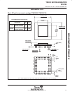
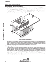
MECHANICAL DATA
68-lead FZ CER-QUAD, ceramic leaded chip carrier package (TMS320E25 only)
This hermetically-sealed chip carrier package consists of a ceramic base, ceramic cap, and a 68-lead frame.
Hermetic sealing is accomplished with glass. The FZ package is intended for both socket- or surface- mounting.
Having a Sn/Pb ratio of 60/40, the tin/lead-coated leads do not require special cleaning or processing
when being surface-mounted.
A B C
MIN MAX MIN MAX MIN MAX
MO-087AA 28
12,32
(0.485)
12,57
(0.465)
10,92
(0.430)
11,56
(0.455)
10,41
(0.410)
10,92
(0.430)
MO-087AB 44
17,40
(0.685)
17,65
(0.695)
16,00
(0.630)
16,64
(0.655)
15,49
(0.610)
16,00
(0.630)
––– 68
25,02
(0.985)
25,27
(0.995)
23,62
(0.930)
24,26
(0.955)
23,11
(0.910)
23,62
(0.930)
NOTES: 1. Glass is optional, and the diameter is dependent on device application.
2. Centerline of center pin, each side, is within 0,10 (0.004) of package centerline as determined by dimension B.
3. Location of each pin is within 0,127 (0.005) of true position with respect to center pin on each side.
4. The lead contact points are within 0,15 (0.006) of being planar.
ADVANCE INFORMATION