


TMS320E25
SPRS010B — MAY 1987 — REVISED NOVEMBER 1990
POST OFFICE BOX 1443 • HOUSTON, TEXAS 77001
63
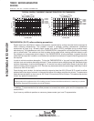
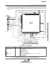
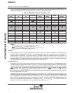
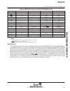
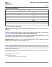
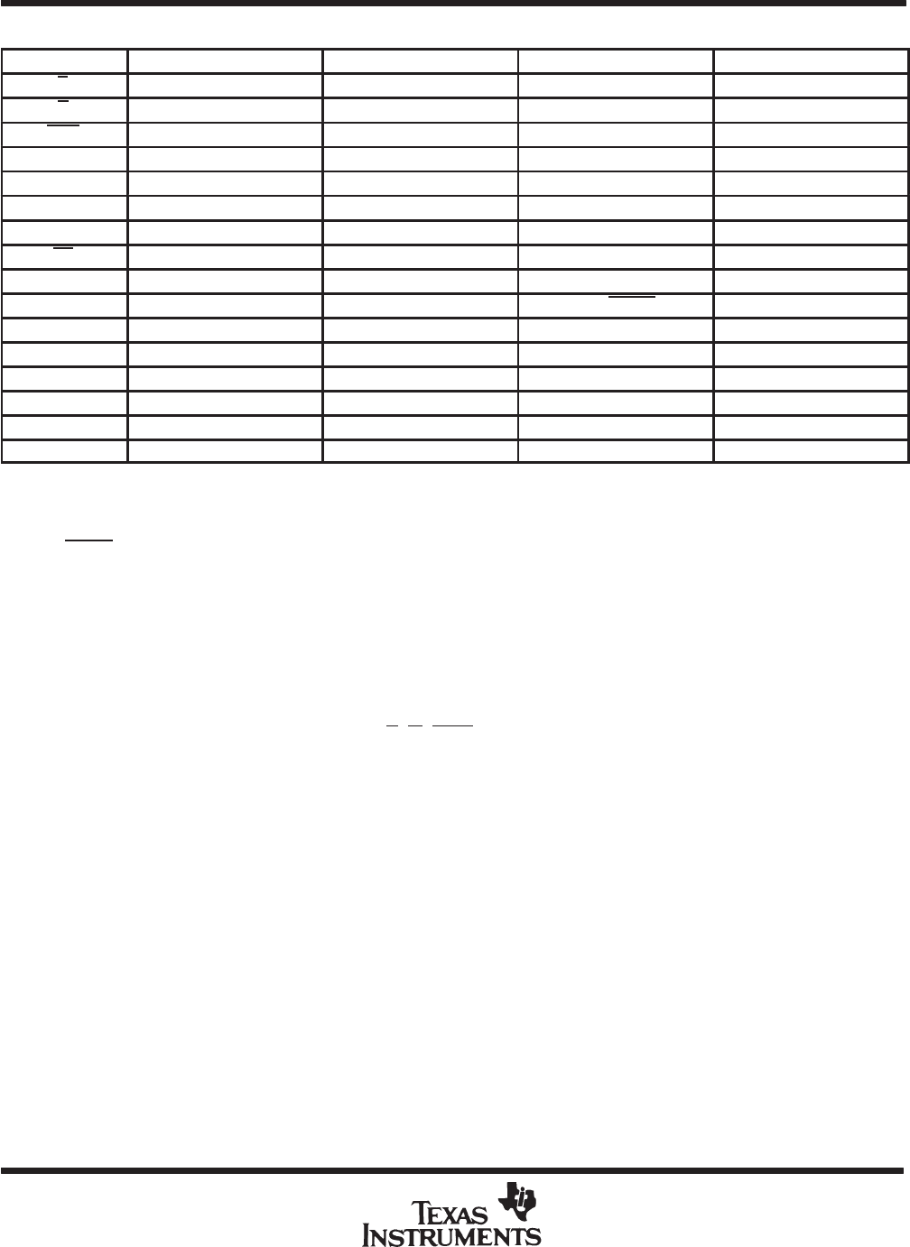
Table 6. TMS320E25 Protect and Verify EPROM Mode Levels
SIGNAL
†
TMS320E25 PIN TMS27C64 PIN ROM PROTECT PROTECT VERIFY
E 22 20 V
IH
V
IL
G 42 22 V
IH
V
IL
PGM 41 27 V
IH
V
IH
V
PP
25 1 V
PP
V
CC
V
CC
61,35 28 V
CC
+
1
V
CC
V
SS
10, 27, 44 14 V
SS
V
SS
CLKIN 52 14 V
SS
V
SS
RS 65 14 V
SS
V
SS
EPT 24 26 V
PP
V
PP
Q8-Q1 18-11 11-13, 15-19 Q8 = PULSE Q8 = RBIT
A12-A10 40-38 2, 23, 21, X X
A9-A7 37, 36, 34 24, 25, 3 X X
A6 33 4 X V
IL
A5 32 5 X X
A4 31 6 V
IH
X
A3-A0 30-28, 26 7-10 X X
†
In accordance with TMS27C64.
LEGEND;
V
IH
= TTL high level; V
IL
= TTL low level; V
CC
= 5 V ± 0.25 V
V
PP
= 12.5 V ± 0.5 V; X = don’t care
PULSE
= low-going TTL level pulse; RBIT = ROM protect bit.
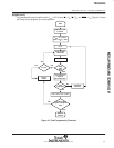
EPROM protect
The EPROM protect facility is used to completely disable reading of the EPROM contents to guarantee security
of propietary algorithms. This facility is implemented through a unique EPROM cell called the RBIT (EPROM
protect bit) cell. Once the contents to be protected are programmed into the EPROM, the RBIT is programmed,
disabling access to the EPROM contents and disabling the microprocessor mode on the device. Once
programmed, the RBIT can be cleared only by erasing the entire EPROM array with ultraviolet light, thereby
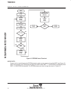
maintaining security of the propietary algorithm. Programming the RBIT is accomplished using the EPROM
protect cycle, which consists of setting the E
, G, PGM, and A4 pins high, V
PP
and EPT to 2.5 V ± 0.5 V, and
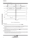
pulsing Q8 low. The complete sequence of operations involved in programming the RBIT is shown in the
flowchart of Figure 12. The required setups in the figure are detailed in Table 6.
ADVANCE INFORMATION