


TMS32020
SPRS010B — MAY 1987 — REVISED NOVEMBER 1990
POST OFFICE BOX 1443 • HOUSTON, TEXAS 77001
25
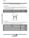
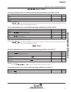
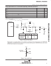
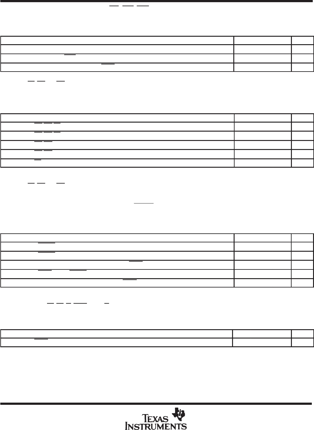
RS, INT, BIO, AND XF TIMING
switching characteristics over recommended operating conditions (see Note 3 and 8)
PARAMETER MIN TYP MAX UNIT
t
d(RS)
CLKOUT1 low to reset state entered 45 ns
t
d(IACK)
CLKOUT1 to IACK valid – 25 0 25 ns
t
d(XF)
XF valid before falling edge of STRB Q – 30 ns
NOTES: 3. Q = 1/4t
c(C)
.
8. RS
, INT, and BIO are asynchronous inputs and can occur at any time during a clock cycle. However, if the specified setup time is met,
the exact sequence shown in the timing diagrams will occur.
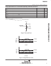
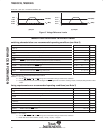
timing requirements over recommended operating conditions (see Note 3 and 8)
MIN NOM MAX UNIT
t
su(IN)
INT/BIO/RS setup before CLKOUT1 high 50 ns
t
h(IN)
INT/BIO/RS hold after CLKOUT1 high 0 ns
t
f(IN)
INT/BIO fall time 15
†
ns
t
w(IN)
INT/BIO low pulse duration t
c(C)
ns
t
w(RS)
RS low pulse duration 3t
c(C)
ns
†
Value derived from characterization data and not tested.
NOTES: 3. Q = 1/4t
c(C)
.
8. RS
, INT, and BIO are asynchronous inputs and can occur at any time during a clock cycle. However, if the specified setup time is met,
the exact sequence shown in the timing diagrams will occur.
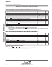
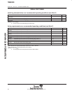
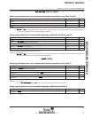
HOLD TIMING
switching characteristics over recommended operating conditions (see Note 3)
PARAMETER MIN TYP MAX UNIT
t
d(C1L-AL)
HOLDA low after CLKOUT1 low –25
†
25 ns
t
dis(AL-A)
HOLDA low to address three-state 15
†
ns
t
dis(C1L-A)
Address three-state after CLKOUT1 low (HOLD mode, see Note 9) 30
†
ns
t
d(HH-AH)
HOLD high to HOLDA high 50 ns
t
en(A-C1L)
Address driven before CLKOUT1 low (HOLD mode, see Note 9) 10
†
ns
†
Value derived from characterization data and not tested.
NOTES: 3. Q = 1/4t
c(C)
.
9. A15-A0, PS, DS, IS, STRB, and R/W timings are all included in timings referenced as “address.”
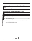
timing requirements over recommended operating conditions (see Note 3)
MIN NOM MAX UNIT
t
d(C2H-H)
HOLD valid after CLKOUT2 high Q – 45 ns
NOTE 3: Q = 1/4t
c(C)
.
ADVANCE INFORMATION