30 DX-700 • User’s Guide • Rev 02
NK==fåíêçÇìÅíáçå
Connectivity Diagrams
`çååÉÅíáîáíó=aá~Öê~ãë
This section provides several sample “single bank” connectivity diagrams.
• Single Bank, Single Input Source, Single Output
• Single Bank, Triple Input Sources, Ungrouped Output
• Single Bank, Single Input Source, Grouped Output
páåÖäÉ=_~åâI=páåÖäÉ=fåéìí=pçìêÅÉI=páåÖäÉ=lìíéìí
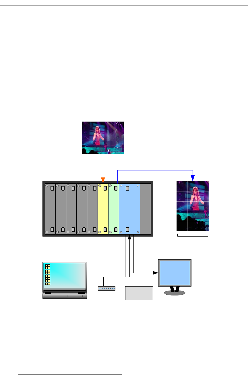
The figure below illustrates a sample DX-700 “single bank” configuration. In this
configuration, the bank consists of a single input module and a single output module. One
input source is mapped to one of the output module’s three output connectors, and is used
to drive a single video wall.
Figure 1-7. Sample system configuration: single input, single output
Blank Panel
Blank Panel
Blank Panel
Output Module
System Module
Power Supply
Input Module
Source 1
LED Wall 1
OLite
Sync
Generator
Laptop PC
(Director Toolset)
DVI or RGB
Monitor
Ethernet
Switch
Blank Panel
Blank Panel


