


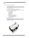
CHAPTER 1: GETTING STARTED
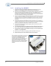
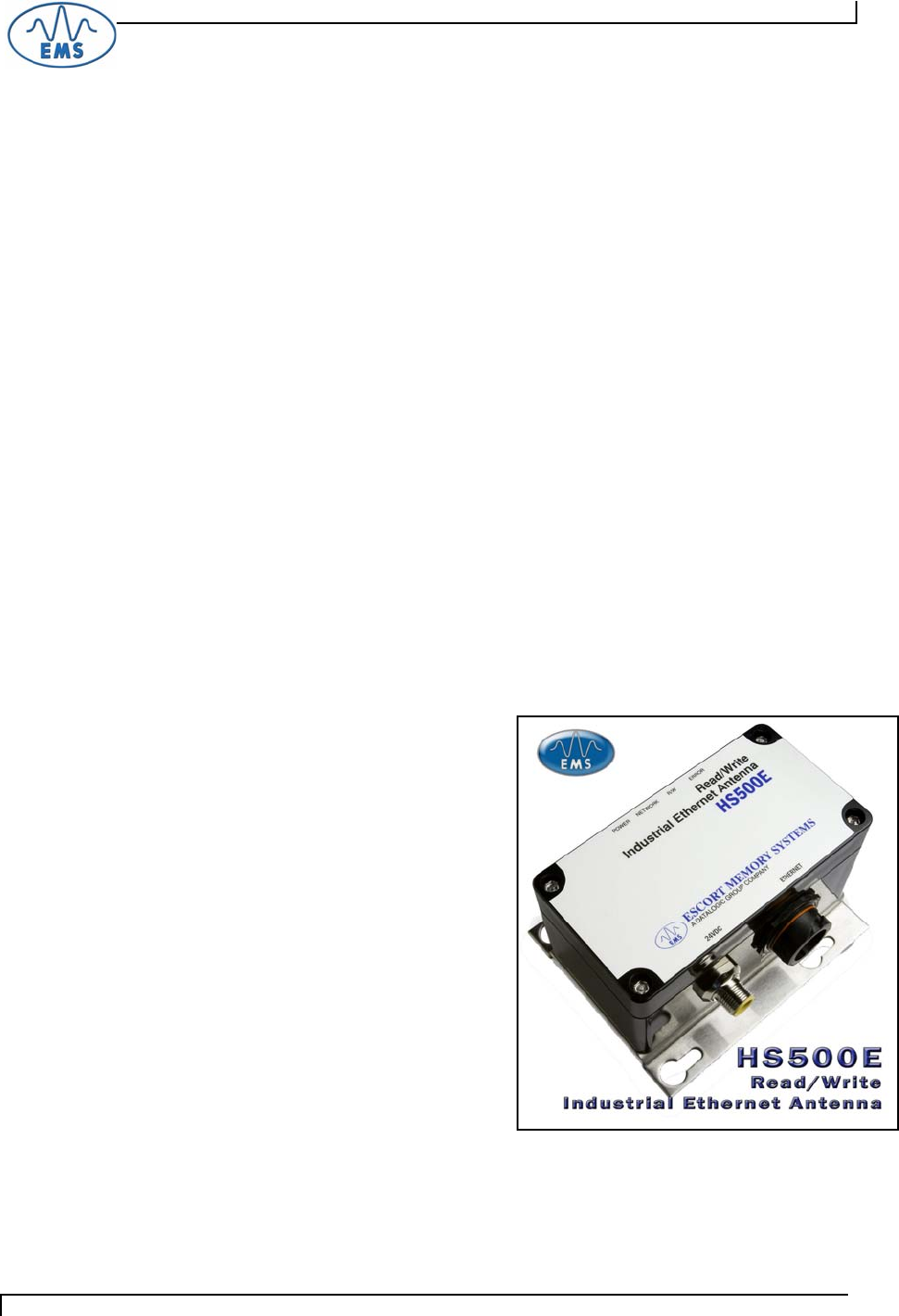
1.4.2 Installing the HS500E
1
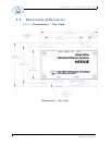
Unpack and inspect the HS500E hardware and accessories. If an item
appears to be damaged, notify your EMS distributor immediately.
2
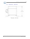
Securely mount the HS500E to your chosen location using four (4) #10 [M5]
screws and matching locking washers and nuts. The HS500E may be
mounted in any orientation, but should be aligned in such a manner that the
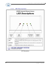
four LED indicators can be seen during operation.
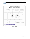
3
Insert one end of a Category 5 Ethernet cable into the IP67 RJ45 connection
housing. Install the RJ45 plug per the included instruction sheet. Attach the
assembled mating connector to the HS500E and twist clock-wise one-half
revolution.
4
Connect the other end of the Ethernet cable to the Host or PLC network. A
crossover cable (P/N: CBL-1479) may be required if connecting the HS500E
directly to a computer (rather than to a switch, hub or router).
5
Connect the female 4-pin M12 power supply cable to the male 4-pin M12
connector on the HS500E.
6
Turn the power supply ON. The Network and Error LEDs will flash 6 times (4
slow, 2 fast), after which the antenna will be ready to receive commands.
7
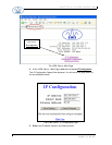
From the Host, connect to the HS500E and assign it a new IP address (see
Chapter 2 – IP Configuration).
8
Note the new IP address on a sticker or label and attach it to the unit.
9
Repeat these steps for each HS500E Antenna to be installed.
Plan to perform a test phase and construct
a small scale, independent network that
includes only the essential devices
required to test your RFID application. To
avoid possible interference with other
devices, do not, at first, connect the RFID
testing environment to an existing office
network.
HS500E – OPERATOR’S MANUAL P/N: 17-1305 REV02 (12-05)
PAGE 17 OF 82