


CHAPTER 6: MODBUS TCP PROTOCOL
CHAPTER 6:
MODBUS
TCP PROTOCOL
One of the most popular and well-proven industrial automation protocols in use today
is Modbus. Modbus TCP allows the Modbus protocol to be carried over standard
Ethernet networks.
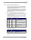
6.1 MODBUS TCP OVERVIEW
Under the Modbus TCP protocol, the HS500E acts as a Modbus Server and the Host
or PLC is the Modbus Client. By utilizing Produce and Consume registers for
mapping commands and responses, data produced by the HS500E is consumed by
the Modbus Client and data produced by the Modbus Client is consumed by the
HS500E.
NOTE:
The Modbus Client (Host or PLC) must connect to the Modbus Server (HS500E)
on port 502.
Maximum number of words transferred to/from an RFID tag per read/write cycle:
100 Words / 200 Bytes
6.1.1 Modbus TCP Command Structure
M
APPING
N
ODE
01
(C
ONSUME
R
EGISTERS
)
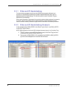
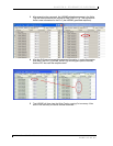
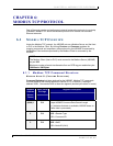
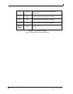
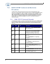
Consume Registers hold data destined for the HS500E. Modbus TCP commands
must be placed in the holding registers of Device ID 1 (i.e. Node 01), starting at
address 40001. Commands utilize at least six registers (double-byte values or words).
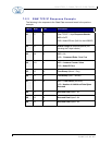
Modbus
Address
(4xxxx /
3xxxx)
Read / Write
Privilege
Register Description
(4000) 1
R/W 2-byte HS500E Consume Data Overall Length
(> 0 indicates that data is available; HS500E clears to
0 after data is processed)
2
R/W MSB = Reader Type
LSB = Command ID
3
R/W MSB = 0x00
LSB = Node ID (0x01)
HS500E – OPERATOR’S MANUAL P/N: 17-1305 REV02 (12-05)
PAGE 52 OF 82