


CHAPTER 5: ETHERNET/IP PROTOCOL
9
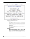
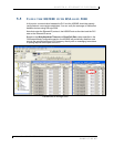
Write Tag Name / Write File Address:
a.
For ControlLogix
:
Specify
a
Write Tag Name
that is 40 characters or
less. The Write Tag Name refers to the name of the Controller Tag in
the PLC where the HS500E will write PLC-bound data for Node 01
(example: EMS_WRITE1). Note: this is not to be confused with writing
to an RFID transponder, which is often referred to as “writing to a tag.”
OR
b.
For SLC505:
Enter
a value in each of the two
Write File Address
fields. The first field contains the number of the (write)
Status File
on
the PLC (for example: N7). The second field contains the
Write File
Offset
. Together these values indicate the location in the PLC’s Status
File where the HS500E will write Host-bound data.
10 Enter
a number between 5 and 6000 to indicate the number of ticks for the
Write Heartbeat Timeou
t (5 ticks = 50ms, 6000 ticks = 1 minute, 0 ticks =
disabled). This value represents the frequency at which the HS500E will write
data to the Write Tag (or the Write File Address) in the PLC when there is
Host-bound data waiting.
Read Settings
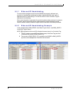
11 Specify
the number of words (between 1 and 100, 0 = disabled) for the
Max
Read Size
. The Max Read Size value represents the maximum number of 2-
byte “words” that the HS500E will attempt to retrieve from PLC memory
during a single command-response cycle. Note: the actual data size required
on the PLC is 3 words larger than the value specified in this field.
12
Read Tag Name / Read File Address:
a.
For ControlLogix
:
Specify
a
Read Tag Name
that is 40 characters or
less. The Read Tag Name refers to the name of the tag in PLC memory
from which the HS500E will retrieve data.
OR
b.
For SLC505:
Enter
a value in each of the two
Read File Address
fields. The first field contains the number of the (read)
Status File
on
the PLC (for example: N7). The second field contains the
Read File
Offset
. Together these values indicate the location in the PLC status file
from which the HS500E will retrieve data.
13 Enter
a value between 5 and 6000 to indicate the number of ticks for the
Read Poll Rate
. (5 ticks = 50ms, 6000 ticks = 1 minute, 0 ticks = disabled)
This value represents the frequency at which the HS500E will poll the Read
Tag (or the Read File Address) in PLC memory. Polling is the act of
repeatedly querying a specific memory location for the presence of new data.
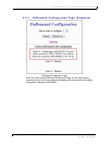
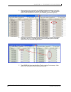
14
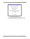
After you have entered the proper information on this page,
click
the
Save
Settings
button. Your changes will be stored and you will be returned to the
OnDemand Configuration Page.
HS500E – OPERATOR’S MANUAL P/N: 17-1305 REV02 (12-05)
PAGE 43 OF 82