


5725A
Instruction Manual
6-6
Access Procedures 6-6.
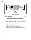
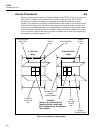
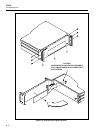
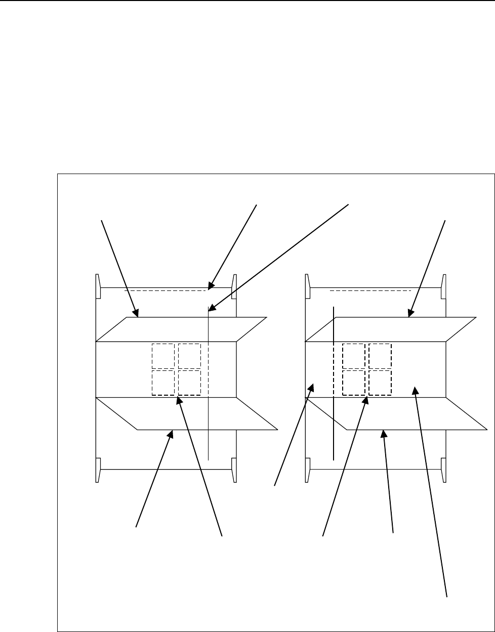
Figure 6-3 shows the location of all major modules in the 5725A. View A is a top view,
and view B is a bottom view. Both views show the covers removed. The 5725A is
constructed so that two modules are completely accessible from the top, and two
modules are completely accessible from the bottom. Each of these four modules can be
lifted out of the chassis and locked in a service position by pivoting the assembly and
inserting two machined pegs into two machined holes in the chassis towards the center
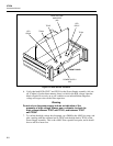
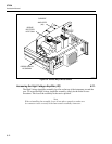
of the instrument. (Figure 6-4 shows the High Voltage Amplifier assembly (A3) in the
Service position.) Once in the service position, a module can be removed completely by
disconnecting all cables attached to it.
A. TOP VIEW
FRONT
B. BOTTOM VIEW
FRONT
CURRENT
AMPLIFIER
(A2)
HIGH VOLTAGE
AMPLIFIER
(A3)
POWER
SUPPLY
(A4)
HIGH
VOLTAGE
SENSE
(A6)
INTERCONNECT
(A1)
DIGITAL
(A5)
POWER
TRANSFORMER
VOLTAGE OUTPUT
SIGNAL
TRANSFORMER
WARNING
LETHAL VOLTAGE ON OUTPUT
TRANSISTOR HEAT SINKS AND
MANY OTHER POINTS THROUGHOUT
THE CHASSIS.
aq15f.eps
Figure 6-3. Assembly Location Diagram