5725A
Instruction Manual
4-16
Fan Supply Section 4-21.
The fan supply uses the same transformer secondary windings as the ±15 and ±20V
supplies. Its own full-wave bridge rectifier diodes create a supply voltage of +25V.
Transistor Q351 is operated near saturation, and provides the measurement point to tell
the CPU whether the fan is running. The output of Q351 is sent to the analog multiplexer
on line -FAN to accomplish this.
Digital Assembly (A5) 4-22.
From a software standpoint, digital circuitry functions as a subset of the 5700A in-guard
CPU. Digital circuitry resides on three assemblies within the 5725A: the Digital
assembly (A5), the High Voltage Sense assembly (A6), and the Current Amplifier
assembly (A2). All the 5725A hardware, including digital, is in-guard, except for the
guard crossing and the CABLEOFF detection circuit.
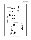
Figure 4-2 is a block diagram of the Digital assembly. The Digital assembly contains
most of the digital circuitry, including the following:
• Microcomputer (Hitachi 6303Y CMOS)
• External RAM (CMOS static)
• External ROM
• EEROM (2Kb X 8)
• Break-detect circuitry
• Power up and reset circuitry
• Watchdog timer circuitry
• Front panel LEDs
• LED decoder and driver
The High Voltage Sense assembly (A6) contains the optoisolator link (guard crossing) to
the 5700A Main CPU and the CABLEOFF circuit.
The Current Amplifier assembly (A2) contains the interface to the digital bus (two
latches and three relay drivers) and a relay driver chip.
Microcomputer 4-23.
The 6303Y CMOS microcomputer is configured for Mode 1 operation, with external
RAM and external ROM. Port 3 provides a common data bus (D00-D07), while port 1
and bits 0 through 5 of port 4 provide the address bus (A0-A13). Bits 6 and 7 of port 4
are address lines A14 and A15.
External RAM 4-24.
External RAM is enabled whenever A15 is high, A14 is low (hex 8000-BFFF), and
either RD* or WR* is true. Reading and writing is controlled by bit 2 of port 7.
External ROM 4-25.
The external ROM (U515) is enabled via ROMSEL* whenever A15 and A14 are high
(hex C000-FFFF). Bit 0 of Port 7 (RD*) is OUTPUT ENABLE*.


