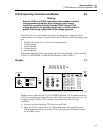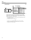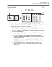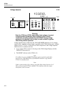
Operating Notes
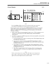
Turning on the 5725A Amplifier
3
3-7
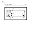
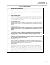
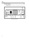
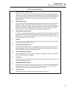
Table 3-2. Rear Panel Features
A CURRENT OUTPUT Binding Posts
The source of all amplified current if the 5725A is configured for rear output. You can set the
5700A to source all its unamplified as well as amplified current through these binding posts. The
LO binding post is isolated from ground when in the current function, and is open-circuited at
other times. Cable and connection recommendations are made in Section 4 of the 5700A
Operator Manual.
B CALIBRATION Switch
A slide switch that enables and disables writing to the nonvolatile memory that stores 5725A
calibration constants. Switching to ENABLE allows writing to the memory, and switching to
NORMAL protects data in memory from being overwritten. The switch must be in the ENABLE
position to store corrections generated during calibration. The switch is recessed to allow a
metrologist to cover it with a calibration seal to guarantee calibrator integrity.
C 5700A CALIBRATOR Connector
Provides the analog and digital interface to the 5700A Calibrator. After connecting to the 5700A,
you control the 5725A from the 5700A front panel or by sending remote commands to the
5700A. Refer to "Using an Auxiliary Amplifier" in Section 4, or for remote operation to Section 5,
of the 5700A Operator Manual for details.
D Fan Filter
Covers the air intake to keep dust and debris out of the instrument. The fan directs a constant
cooling air flow throughout the chassis.
E Line Voltage/Fuse Rating Label
Shows the various settings of the line voltage switches, and the correct replacement fuse for
operating voltages of 110 (90 to 132) and 220 (180 to 264) volts ac. Refer to "Accessing the
Fuse" in Section 2 for the fuse replacement procedure.
F Line Voltage Selection Switches
Select the operating line voltage. Refer to "Selecting Line Voltage" in Section 2 for instructions
on how to select operating line voltage.
G Fuse Holder
The line power fuse. Refer to "Accessing the Fuse" in Section 2 for fuse rating information and
the fuse replacement procedure.
H CHASSIS GROUND Connector
If the 5725A is the location of the ground reference point in a system, the CHASSIS GROUND
binding post can be used for connecting other instruments to earth ground. (The chassis is
connected to earth ground through the three-conductor line cord.)
I Line Power Input
A grounded male three-prong connector that accepts the line power cord.


