


4-1
Chapter 4
Theory of Operation
Title Page
4-1. Introduction .......................................................................................... 4-3
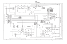
4-2. Overall Functional Description............................................................ 4-3
4-3. 1100V AC Range Functional Description....................................... 4-5
4-4. 11A Range Functional Description.................................................. 4-6
4-5. Operation in the 11A DC Range.................................................. 4-7
4-6. Operation in the 11A AC Range.................................................. 4-7
4-7. Voltage and Current Standby Modes............................................... 4-7
4-8. Voltage Standby........................................................................... 4-7
4-9. Current Standby........................................................................... 4-7
4-10. How the 5700A and 5725A Communicate...................................... 4-8
4-11. Description of the Out-Guard Lines (5725A Side) ..................... 4-8
4-12. Description of the In-Guard Lines............................................... 4-9
4-13. Functional Summaries by Assembly................................................ 4-10
4-14. Detailed Circuit Description ................................................................ 4-11
4-15. Interconnect Assembly (A1) ............................................................ 4-11
4-16. Power Supply Assembly (A4).......................................................... 4-12
4-17. High Voltage Supply Section ...................................................... 4-13
4-18. Switching Section........................................................................ 4-14
4-19. Current-Limit Section.................................................................. 4-15
4-20. System Supply Section ................................................................ 4-15
4-21. Fan Supply Section...................................................................... 4-16
4-22. Digital Assembly (A5)..................................................................... 4-16
4-23. Microcomputer ............................................................................ 4-16
4-24. External RAM.............................................................................. 4-16
4-25. External ROM.............................................................................. 4-16
4-26. EEROM ....................................................................................... 4-18
4-27. Data Latch.................................................................................... 4-18
4-28. Strobe Lines................................................................................. 4-18
4-29. Led Driver.................................................................................... 4-18