Theory of Operation
Overall Functional Description
4
4-7
Operation in the 11A DC Range 4-5.
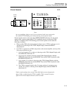
For the dc current function, the 5700A is configured for the dc 2.2V range. The 5700A
2V dc range drives an error amplifier with an input impedance of 40 kΩ. The gain of this
amplifier is determined by this 40 kΩ resistor with a 4 kΩ feedback resistor, and the
value of the precision shunt. The 5725A uses a 0.02Ω shunt for the 11A function. There
is no feedback to the 5700A.
The 5725A monitors the error amplifier output voltage using the 16-channel multiplexer.
One channel of the multiplexer, ICOMPL M, is scanned every 30 milliseconds or faster,
with its output compared to -2V from the DAC. If the peak error amplifier output is
more negative than the dac voltage, MONCOMP goes LOW and is read by bit 6 of port
5 of U507, the CPU. This indicates an overload condition, and lights the OVERLOAD
LED. If a later scan shows the same result, the CPU trips the Current Amplifier into
standby and reports this condition to the 5700A.
A soft-start from standby to operate transitions reduces sudden current changes. This
allows the 5725A to drive inductive loads such as power meters and clamp-on type
current probes.
Operation in the 11A AC Range 4-6.
For ac current operation, input to the 5725A comes from the 5700A Oscillator. The
5700A Oscillator is configured for the 2.2V ac range, with sensing back to the 5700A
Oscillator coming from the current shunt through the calibration amplifier circuit (on the
Current Assembly).
Voltage and Current Standby Modes 4-7.
When a change in output function is selected, the 5725A goes through voltage or current
standby mode before connecting the output to the 5725A binding posts, or to the 5700A.
Voltage or current standby allows for local sensing within the 5725A, and for
establishment of a known input condition in current and ac voltage.
Voltage Standby 4-8.
In voltage standby, the 5700A binding posts are completely disconnected from the rest
of the instrument circuitry, and the 5725A high voltage output and sense lines (B-OUT
HI and B-SENSE HI) are disconnected from the 5725A/5700A connector. The High
Voltage Amplifier remains powered from the high voltage supply, but its input is
grounded by pulling CLAMPD, and its output (MV OUT) is disconnected from the
output transformers. Analog monitor circuitry continues to check the voltage and current
on the high voltage supplies as well as the heat sink temperatures and cable integrity. It
prevents the 5725A from switching to operate if a fault is present.
Current Standby 4-9.
In current standby, the binding posts are disconnected from the instrument circuitry, but
all 5725A/5700A connections are made as in the operate mode. In dc current standby,
the 5700A DAC supplies a voltage that corresponds to the dc current selected. In ac
current standby, 5725A relay settings are identical to those for dc current standby. The
5700A Oscillator supplies an ac voltage level that corresponds to the selected output
current and frequency.


