


Troubleshooting
Manual Tests for Fault Isolation
7
7-7
Problems 1 or 2: Fault at Power-Up or When Entering Voltage Standby 7-5.
Proceed as follows to isolate the problem in these conditions:
1. If the 5700A is reporting a fault, determine if it is an analog monitor fault from
Table 7-2. If the fault is not in Table 7-2, skip to step 2. (See Table 7-1 for
explanations of fault codes.)
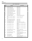
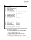
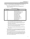
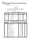
Table 7-2. Analog Monitor Faults
FAULT NO. MESSAGE
209 5725 Current Heatsink Too Hot
210 Output Tripped To Standby
211 5725 Current Compliance Voltage Too High
212 5725 Current Compliance Voltage Too High
213 5725 +400V Supply Did Not Shut Off
214 5725 -400V Supply Did Not Shut Off
215 5725 Voltage Heatsink Too Hot
216 Output Tripped To Standby
217 5725 +400V Supply Too Low
218 5725 +400V Supply Too High
219 5725 -400V Supply Too Negative
220 5725 -400V Supply Too Positive
221 5725 +400V Supply Current Too High
222 Output Tripped To Standby
223 5725 -400V Supply Current Too High
224 Output Tripped To Standby
225 5725 Fan Not Working
a. With an oscilloscope, check TP152 (DAC OUT) for the waveform shown facing
Section 9 with the High Voltage Sense Assembly (A6) schematic.
b. If the waveform is present, suspect an abnormal analog input into U151 on the
High Voltage Sense Assembly (A6). See Table 4-3 for voltage limits of the
analog inputs for standby operation.
c. If the waveform is not present, short TP510 to DCOM on the Digital assembly.
This tells the CPU to ignore all analog monitor faults and run all other tests.
Check for any new fault codes that indicate the problem.
d. If the waveform is still not present, the High Voltage Sense Assembly (A6) is
likely to be at fault, specifically, the circuitry that includes U151, U155, U156,
U153, and U154.
2. If not an analog monitor fault, is it a high voltage supply (Fault 234) or CLAMPS*
(Fault 226) fault? If yes and in standby mode, suspect the Power Supply assembly
(A4). If yes and in voltage standby mode, suspect the High Voltage Amplifier (A3)
and the high voltage output transistors.
3. If the error on the 5700A is not an analog monitor fault, high voltage supply (Fault
234), or CLAMPS* (Fault 226) fault, or if no fault is reported by the 5700A, check
for communications activity at pins 12 and 13 of U507 on the Digital assembly (A5).
The waveform should appear as shown facing the Digital schematic as waveform 4.
If there is no activity, suspect the communication circuitry on the High Voltage
Sense Assembly or the Digital assembly.