Theory of Operation
Detailed Circuit Description
4
4-19
Break-Detect Circuitry 4-31.
The 6303Y divides the 4.9152-MHz crystal frequency by four to create the 1.2288-MHz
ECLK. This signal serves as the clock for the 74HC4020 counter (U506), which is
configured as a divide-by-16384. The RECEIVE line is usually high, except for the brief
interval when characters are being transmitted. As long as the low state is less than 13.34
ms, RECEIVE holds the CLR of the 74HC4020 TRUE. However, if communication
between the 5725A Amplifier and the 5700A Calibrator fails, the 5700A attempts to
reset the 5725A by sending a break (holding RECEIVE low for greater than 26.7 ms).
This action causes the 74HC4020 counter output (BREAK) to go high. Signal BREAK is
NOR’ed with CABLEOFF from the High Voltage Sense assembly (A6); either signal
causes a NON-MASKABLE INTERRUPT to the 6303Y. The 5700A also uses BREAK
to reset the 5725A.
Power Up and Reset Circuitry 4-32.
Reset and glitch-detection circuitry primarily consists of U508, a TL7705A. This chip
detects if the power supply falls below 4.5V, if a reset input from a momentary contact
switch occurs, or if there is an output from the watchdog timer. Any combination of
these conditions resets the board via RESET* for 130 ms.
Watchdog Timer 4-33.
Watchdog circuitry contains a 4538 Dual Monostable Multivibrator. The first
multivibrator (U509A) is configured as a 300 ms retriggerable one-shot that can fire a
second 3 ms one-shot (U509B). Control line STROBE 2 of the 6303 (bit 1, port 6)
retriggers the first one-shot every 50 ms and refreshes the high voltage relay driver. If
STROBE 2 is stuck high or low during operation, the first one-shot is no longer
retriggered, and its output transitions low. The second one-shot, configured to trigger on
a falling edge, now sends a pulse via RESIN* to the TL7705A reset IC U508. This
action forces the reset circuit to pull a hard reset on the 6303Y for 130 ms.
The first trigger to the 4538 occurs when the 7705A RESET* line makes a transition
from low to high. During normal operation, STROBE 2 prevents another reset by
retriggering the first one-shot well before the 300 ms timeout. The watchdog fires only if
the CPU is executing erroneous code which does not activate STROBE 2.
Current Amplifier Assembly (A2) 4-34.
The Current Amplifier assembly enables the 5725A to extend the current output range of
the 5700A Calibrator to ±11A dc or 11A ac. The 5700A drives the Current Amplifier
assembly input through the 5725A interface cable. There are no user input terminals.
Output current is available at binding posts on the 5725A front or rear panel. Selection of
front or rear 5725A binding posts is done by unplugging one cable and plugging in
another cable on the Current Amplifier assembly inside the 5725A chassis. Additionally,
relays on the Current Amplifier assembly can route the 5700A current source to the
5725A output terminals, if so selected at the 5700A front panel (or by remote command).
The Current Amplifier assembly has five distinct sections: the error amplifier, output,
control, monitor, and power supply. Each section is first briefly described, then
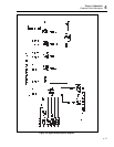
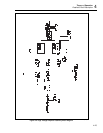
described in detail in the following paragraphs. Refer to Figure 4-3, a block diagram of
the Current Amplifier assembly, to see the interrelationship of the following function
blocks.


