


C4658M-C (6/10) 25
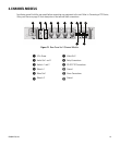
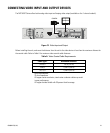
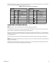
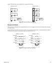
Table B identifies the pin assignments for the terminal block. An arrow on the rear panel identifies pin 1; on the terminal
block, pin 1 is the left-most lead on the top row (refer to Figure 15).
CONNECTING A PTZ DEVICE (PELCO D)
NOTE: To connect a Coaxitron PTZ device, refer to Connecting Video Input on page 22.
The NET5400T Series supports serial camera control using Pelco D (RS-422) for a PTZ device. You can connect only one
serial PTZ device to a video encoder. The default Pelco D device address is 1.
When the unit receives a camera control command, it transmits that command to the PTZ device. In 4-wire installations,
the encoder also receives data from the PTZ device, including camera status and alarm states. It then transmits that data
to the command center.
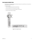
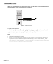
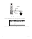
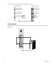
Figure 16 shows how to wire the unit to a Spectra dome (refer to Table B for the specific connector pin assignments).
NOTE: When connecting a PTZ device to the unit, connect the TX+ and TX– leads to the RX+ and RX– leads between the
encoder and the PTZ device.
By default, the encoder identifies any PTZ device as a fixed camera. You must configure the encoder before you can use
the PTZ device; refer to the software configuration/operation manual.
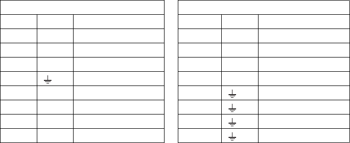
Table B. PTZ, Relay, and Alarm Pin Assignments
Top Row Bottom Row
Pin Label Lead Pin Label Lead
1 NC Relay Normally Closed 9 TX+ RS-422 Data TX+
2 C Relay Common 10 TX– RS-422 Data TX–
3 NO Relay Normally Open 11 RX– RS-422 Data RX–
4 Ground 12 RX+ RS-422 Data RX+
5A
1 Alarm 1 13 Ground
6A2 Alarm 2 14 Ground
7A
3 Alarm 3 15 Ground
8 A4 Alarm 4 16 Ground