


Connections
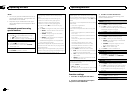
WARNING
! Usespeakersover 50W(output value)and
between4W to8W (impedancevalue).Do
notuse1 Wto3 Wspeakers forthisunit.
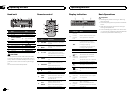
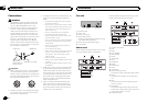
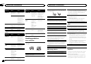
! Theblackcable isground.When installing
thisunitor poweramp(sold separately),
makesureto connecttheground wirefirst.
Ensurethatthe groundwireis properlycon-
nectedtometal partsof thecar’s body.The
groundwireof thepower ampandthe oneof
thisunitor anyotherdevice mustbecon-
nectedtothe carseparatelywith different
screws.If thescrewfor thegroundwire loos-
ensor fallsout, itcouldresult infire, genera-
tionofsmoke ormalfunction.
Ground wire
Metal parts of car’s bod
y
POWER AMP
Other devices
(Another electronic
device in the car)
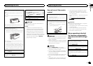
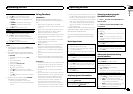
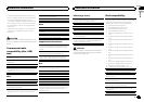
Important
! Wheninstallingthis unitin avehiclewithout
anACC(accessory)position ontheignition
switch,failureto connectthered cabletothe
terminalthatdetectsoperationof theignition
keymayresult inbatterydrain.
O
N
S
T
A
R
T
O
F
F
ACCposition NoACCposition
! Usethisunit witha 12-voltbattery andnega-
tivegroundingonly.Failure todoso mayre-
sultina fireor malfunction.
! Topreventashort-circuit, overheatingormal-
function,besure tofollowthe directions
below.
— Disconnectthenegativeterminalofthebat-
terybeforeinstallation.
— Securethewiringwithcableclampsoradhe-
sivetape.Wrapadhesivetapearoundwiring
thatcomesintocontactwithmetalpartsto
protectthewiring.
— Placeallcablesawayfrommovingparts,
suchasthegearshiftandseatrails.
— Placeallcablesawayfromhotplaces,such
asneartheheateroutlet.
— Donotconnecttheyellowcabletothebattery
bypassingitthroughtheholetotheengine
compartment.
— Coveranydisconnectedcableconnectors
withinsulatingtape.
— Donotshortenanycables.
— Nevercuttheinsulationofthepowercableof
thisunitinordertosharethepowerwith
otherdevices.Thecurrentcapacityofthe
cableislimited.
— Useafuseoftheratingprescribed.
— Neverwirethenegativespeakercabledirectly
toground.
— Neverbandtogethernegativecablesofmulti-
plespeakers.
! Whenthisunit ison,control signalsaresent
throughtheblue/white cable.Connectthis
cabletothe systemremotecontrol ofanex-
ternalpoweramp orthevehicle’s auto-anten-
narelaycontrol terminal(max.300 mA12V
DC).If thevehicleis equippedwitha glass
antenna,connectit totheantenna booster
powersupplyterminal.
! Neverconnectthe blue/whitecableto the
powerterminalof anexternalpower amp.
Also,neverconnectit tothe powerterminal
ofthe autoantenna.Doing somayresult in
battery drainora malfunction.
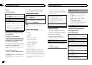
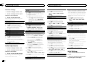
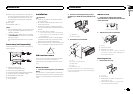
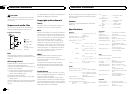
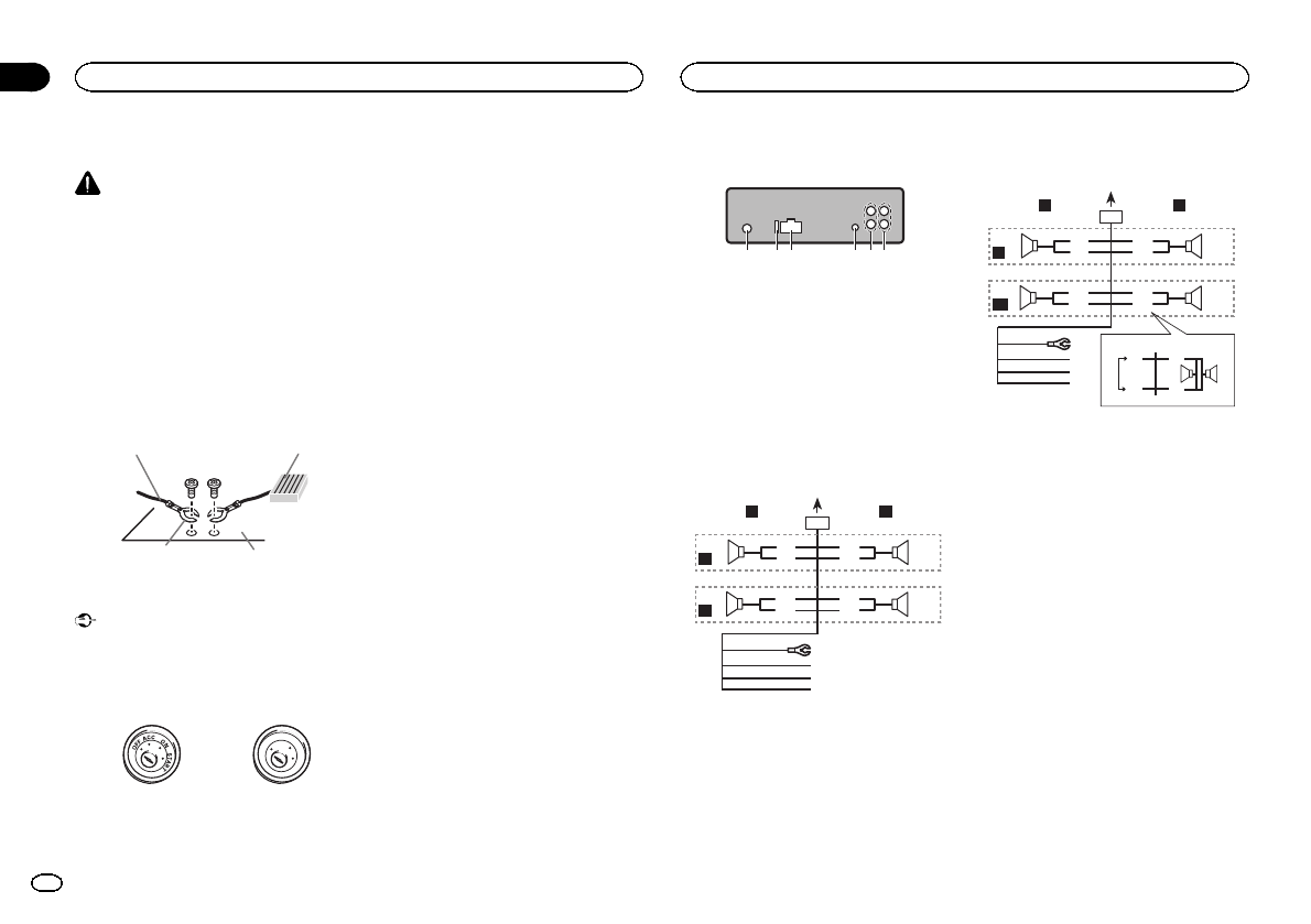
This unit
123 4 56
1 Antennainput
2 Fuse(10A)
3 Powercordinput
4 Wiredremoteinput
Hard-wiredremotecontrol adaptorcanbe
connected(soldseparately).
5 Rearoutputorsubwooferoutput
6 Frontoutput
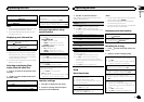
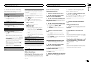
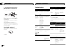
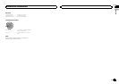
Power cord
Performtheseconnections whennotconnect-
ingarear speakerleadto asubwoofer.
1
8
9
c
d
6
32
4
5
7
a
b
e
f
h
g
LR
F
R
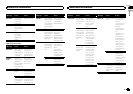
Performtheseconnections whenusinga sub-
wooferwithout theoptionalamplifier.
1
8
9
c
d
6
32
4
7
a
b
a
b
e
f
h
g
LR
F
SW
i
j
d
c
k l
1 To powercordinput
2 Left
3 Right
4 Frontspeaker
5 Rearspeaker
6 White
7 White/black
8 Gray
9 Gray/black
a Green
b Green/black
c Violet
d Violet/black
e Black(chassisground)
Connecttoa clean,paint-freemetal location.
f Yellow
Connecttothe constant12V supplytermi-
nal.
g Red
Connecttoterminal controlledbyignition
switch(12V DC).
h Blue/white
Connecttosystem controlterminalof the
powerampor auto-antennarelaycontrol ter-
minal(max.300 mA12V DC).
i Subwoofer(4Ω)
Installation
03
12
Section
Installation
En